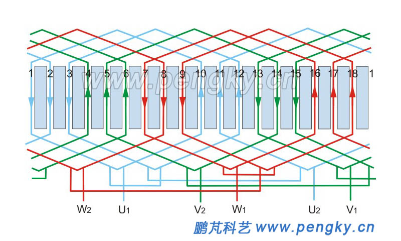
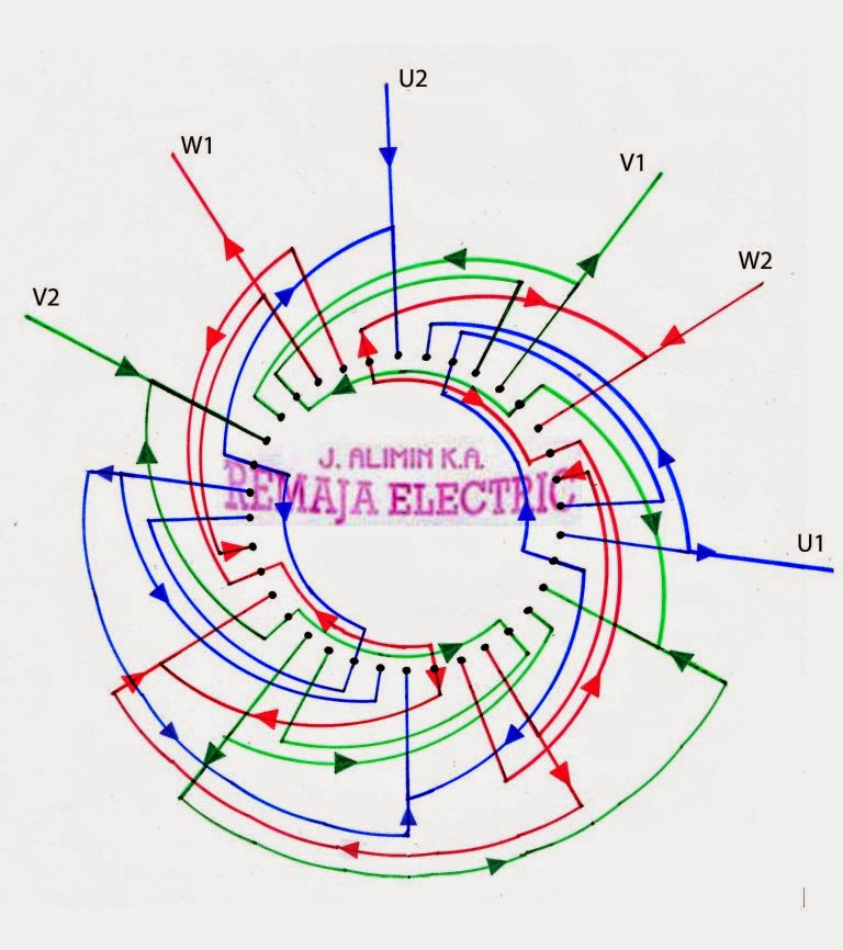
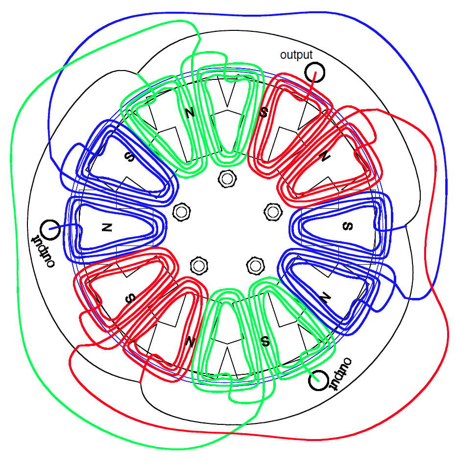
3 phase chakki motor 36 slot 1440 rpm connection diagram in hindi type 1delta connection duration. A three phase motor is more efficient than a single phase motor because of the peculiarities of alternating current ac.

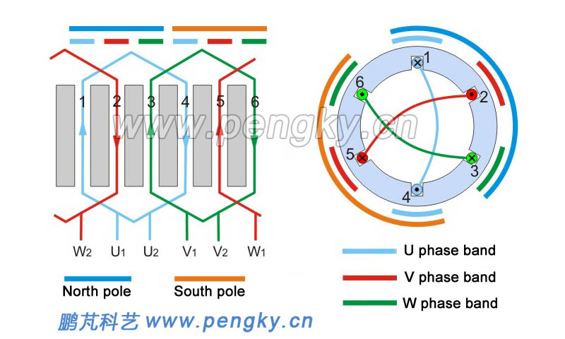
3 Phase Induction Motors With Poles Not Equal To 3x
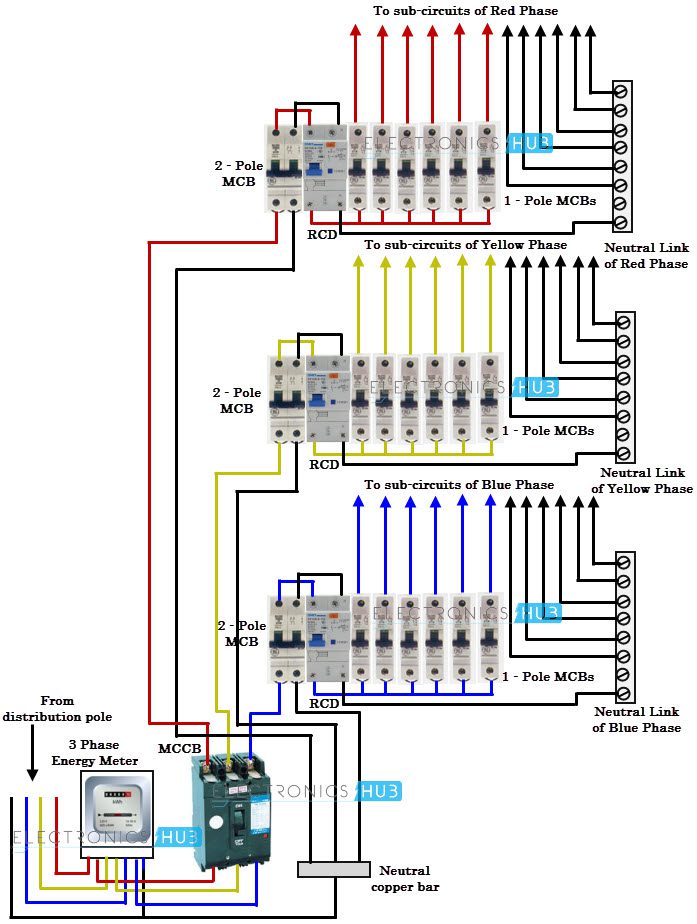
3 phase 6 pole motor wiring diagram. Split phase motor wiring diagram. Discover ideas about electrical projects. Capacitor motor single phase wiring diagrams always use wiring diagram supplied on motor nameplate. When a motors power supply is brought in from three wires instead of just one with the power delivery cycling through each of these in sequence hence the a part of ac it permits an effective power level that is 3 times higher about 1728 times higher than a. Multispeed motor connections76 77 1 phase76 3 phase76 77 programmable lighting controllers78 class 886578. Other fans as shown brown black blue m 1 greeny ellow brown cap black ce31 only single phase ac motor with capacitor blue or grey a n sildes these diagrams mainly apply to external rotor motorsbut some standard.
2 phase and 3 phase size 00 to 5 44 3 phase size 6 45 3 phase size 7 46. Hi tech technical expert rao ji 22784 views 1812. The split phase motor can be found in applications requiring 120 hp up to 13 hp meaning it can turn anything from blades on a ceiling fan washing machines tubs blower motors for oil furnaces and small pumps. 3 pole circuit breaker cb. I think i have this right but its always best to check before applying power. Now for the purposes.
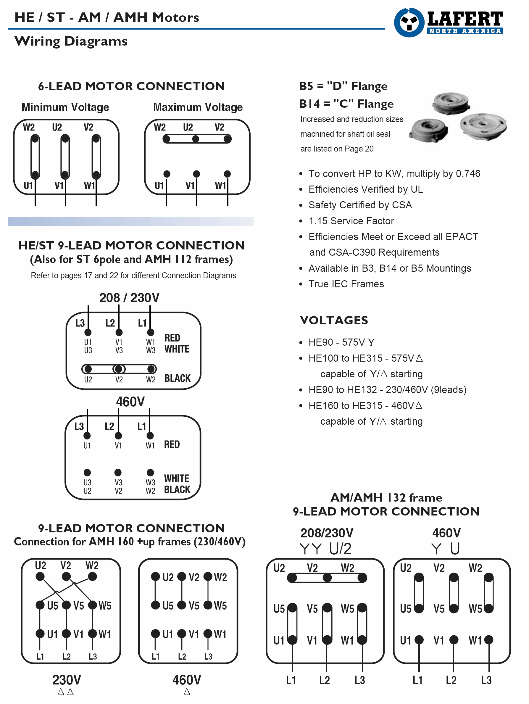
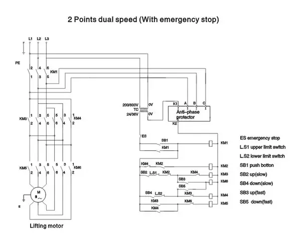
W2 cj2 ui vi wi w2 cj2 ui vi wi a cow voltage y high voltage z t4 til t12 10 til t4 t5 ali l2 t12 ti blu t2 wht t3org t4 yel t5 blk t6 gry t7 pnk. I believe i need to wire u1 v1 w1 to power and leave u2 v2 w2 disconnected. Assortment of 3 phase motor contactor wiring. The below wiring diagram shows how we would assemble a complete motor starter with a startstop button for a single phase motor utilizing a 3 pole contactor. 1ø wiring diagram diagram er4 1ø wiring diagrams m 1 lne 3 active wires plus auto reset thermal contacts codes. Below is the motor data plate and whats left of the wiring diagram.
The centrifugal switch is a normally close control device that is. Using this method the current is balanced between the 3 poles on the overload. Yet with the help of this step by step guide this task will be become as easy as counting to five. How to wire a baldor 3 phase motor. I am trying to wire up a two speed 6 wire 3 phase motor to run at its highest speed. Then you connect the 2 motor leads to t1 and t3.
Break your circuit l n e through your contactor. Wiring a baldor motor can at first glance look to be a very intimidating task.

