Also it is stated 2011 feed through conductors splices and taps are permitted in the wiring space where conditions 1 through 3 are met the wiring space of enclosures for switches or. 25 best electrical wiring images on pinterest.
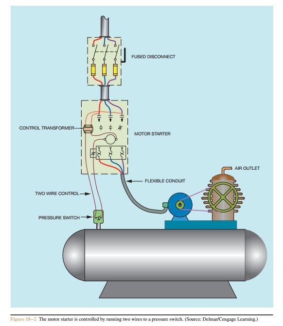
Motor Control For 3 Phase Induction Motors
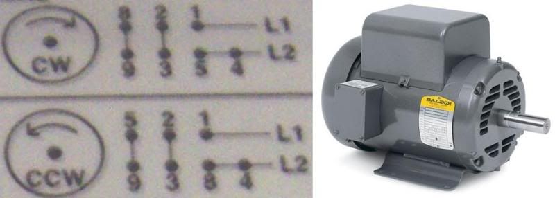
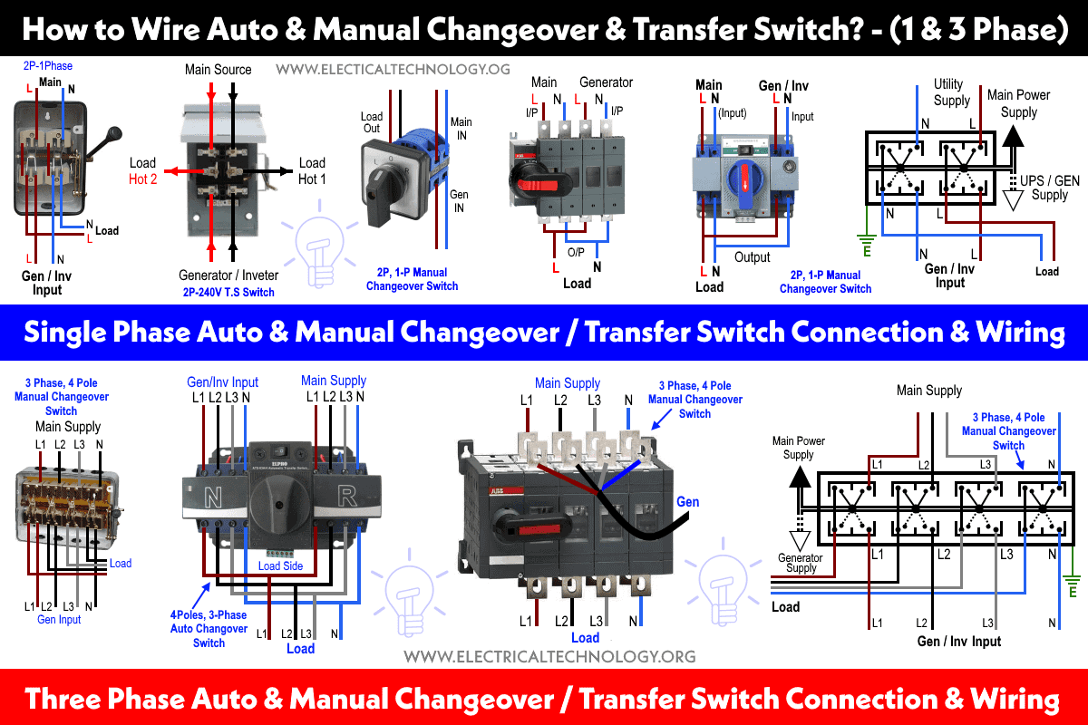
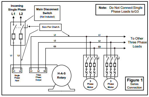
3 phase disconnect switch wiring diagram. Wiring diagram for isolator switch save rv battery disconnect switch. Interconnecting wire courses might be shown approximately where specific receptacles or fixtures should get on a typical circuit. 3 phase disconnect switch wiring diagram architectural electrical wiring diagrams reveal the approximate areas as well as affiliations of receptacles lights and permanent electrical solutions in a structure. It shows the parts of the circuit as simplified shapes and also the power and signal connections between the devices. 3 phase disconnect switch wiring diagram sample 3 phase wiring diagram inspirational. Stop start with mini plc and on switch wiring diagram.
Its also possible for a home to have a service disconnect on the outside of the home while the main service panel with its own main breaker is inside the home. The next video is starting stop. Step 3 hook up the disconnect. Remove the double contact pullout inside figure 6 to open both contacts of the switch. How to connect the 3 phase controller or failure relay to main board wiring diagram. Leviton n3603 60 amp 600 volt toggle in type 3r enclosure three pole ac motor starting switch suitable as motor disconnect industrial grade black 30 out of 5 stars 2 11320 113.
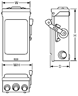
Collection of 3 phase disconnect switch wiring diagram. 43 lovely motor installation wiring. Figure 5 shows a pullout switch with the cover lifted and. The disconnect switch is shown in figures 5 6 and 7. A wiring diagram is a simplified traditional photographic representation of an electrical circuit. This disconnect may be a special breaker switch housed in an exterior box enclosure or it may simply be the main circuit breaker on the homes main service panel.


