Motor starters are types switches either electromechanical or solid state that are designed to start and stop the motors by providing the necessary power to the motor and preventing the motor to draw. Refer to the motor manufacturers data on the motor for wiring diagrams on standard frame ex e ex d etc.

Direct Online Starter Construction Working Advantages
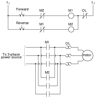
3 phase motor starter wiring diagram pdf. Is a typical wiring diagram for a three phase mag netic starter. The following diagram is shown for 3 phase motor control of a delta star connection. Wye delta open transition 3 phase motors. A wiring diagram is a streamlined conventional photographic representation of an electrical circuit. Phase 220 vac motor wiring diagrams wiring diagram 3 phase motor wiring diagram 12 leads wiring diagram contains numerous comprehensive illustrations that present the relationship of varied things. 2 phase and 3 phase size 00 to 5 44 3 phase size 6 45 3 phase size 7 46.
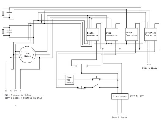
It shows the parts of the circuit as simplified shapes and also the power and also signal links in between the tools. Assortment of 3 phase motor starter wiring diagram pdf. They do not indicate the physical relation. In this tutorial we will show the star delta y δ 3 phase induction ac motor starting method by automatic star delta starter with timer with schematic power control and wiring diagram as well as how star delta starter works and their applications with advantages and disadvantages. Star delta starter y δ is a common type of three phase 3 phase induction motor starters generally used in low starting torque motors. Multispeed motor connections76 77 1 phase76 3 phase76 77 programmable lighting controllers78 class 886578.
33 l1 l2 l3 n suggested wiring arrangement selector switch hi speed contactor overload overload lo speed contactor these diagrams are current at the time of publication check the wiring diagram supplied with the motor. W2 cj2 ui vi wi w2 cj2 ui vi wi a cow voltage y high voltage z t4 til t12 10 til t4 t5 ali l2 t12 ti blu t2 wht t3org t4 yel t5 blk t6 gry t7 pnk. Capacitor motor single phase wiring diagrams always use wiring diagram supplied on motor nameplate. 1 the following links are pre fitted to the starter. Line diagrams also called schematic or elementary dia grams show the circuits which form the basic operation of the controller. It uses three contactors an overload relay one auxiliary contact block a normally open start pushbutton a normally closed stop pushbutton an on delay timer of 0 20 seconds and a power supply with a fuse.
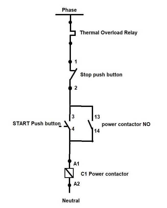
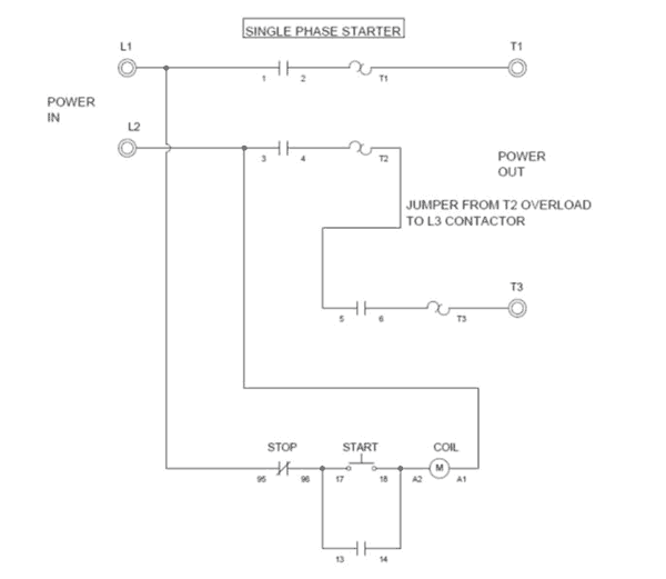
Typical wiring diagram line diagrams show circuits of the operation of the controller. A2 14 18. Wiring diagram since wiring connections and terminal markings are shown this type of diagram is helpful when wiring the. Wiring of the direct on line dol motor starter 1 three phase supply 230volt coil see wiring diagram. All other control and power connections have to be made by the installer. 13 17 with a flying lead to be connected to overload terminal 95.


