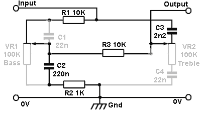
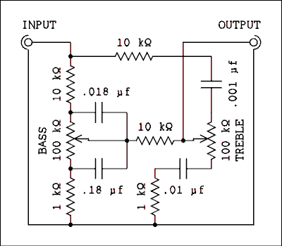
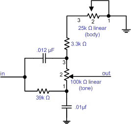
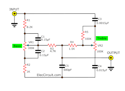
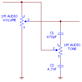
Then there is capacitors c12 serves to filter the voltage. Passive tone control circuit.
Simple Audio Tone Control Circuit
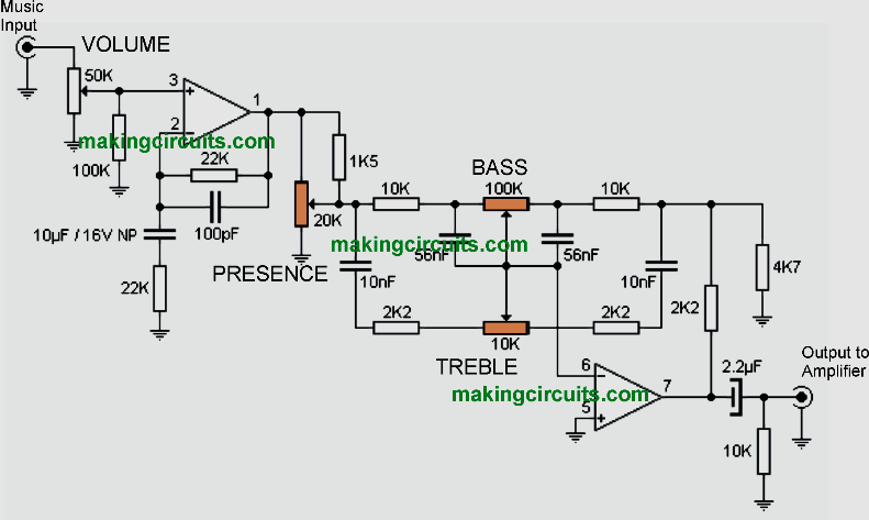
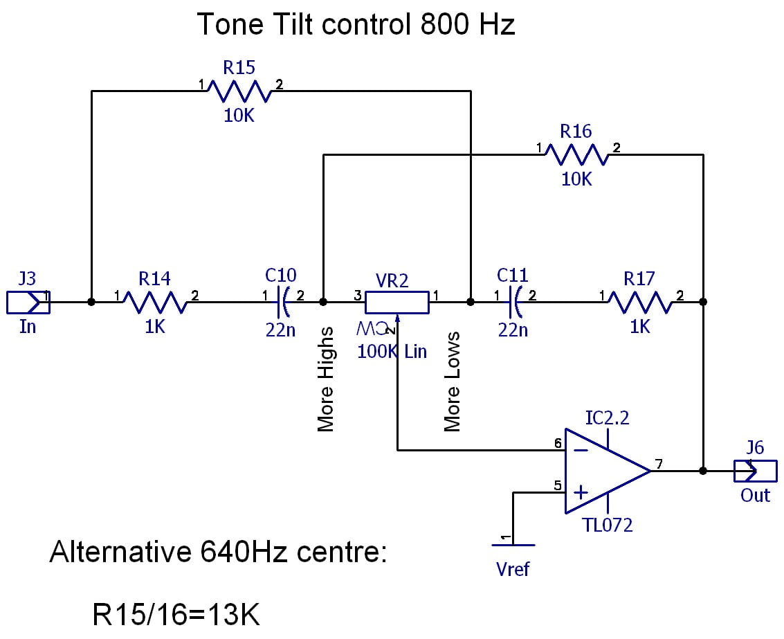
Passive tone control circuit diagram. The circuit given here can give a maximum cut or boost of around 12 db at 10 khz treble and 50hz bass. T1 also provides a certain degree of pre amplification to the. 1 or are constructed as part of the negative feedback loop around a gain block using the general design due to baxandall. This is a passive tone control circuit. The first diagram shown below is perhaps the simplest of its kind. Now you can control the bass treble and volume by rotating three potentiometer on the circuit.
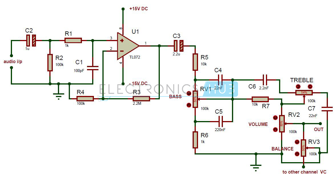
As application of this tone controller circuit it. This simple tone control circuit is designed based on the famous baxendall tone control circuitry. The audio tone control circuit mainly consists of two sections one is amplifier and other is passive tone control circuit. No the expansion but will give kind equipment r and c. It perform filter frequency then the circuit that build easy and must not use power supply. 422 which is an analogue circuit providing independent control of bass and treble frequencies.
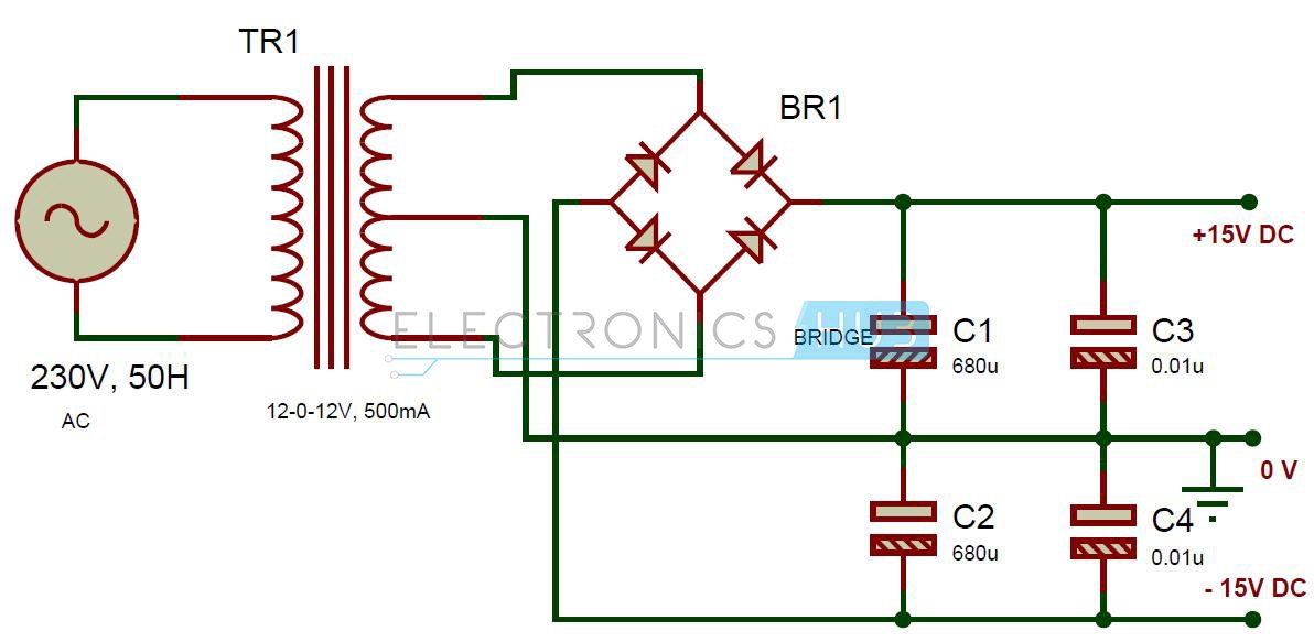
Also both bass and treble can be independently adjusted. First the power supply has diodes d1 d4 is connected as bridge rectifier so can apply power all type acdc. Typical circuit layouts for active tone control are shown in figs. The circuit is entirely based on passive components and the performance is very superior. To operate the circuit connect the components as per the circuit diagram give 15v and 15v supply to tl072 opamp and give audio input from mobile by connecting 35 mm audio jack to the circuit. By can concede the porch with part power amplifier of output immediately.
It uses just one transistor as the active part and a few other common passive tone control components. Working of simple tone control. Working with 2 sections the power supply and the tone controls. Transistor q1 bc109 and its associated components r1. These are either of the passive type of which a typical circuit layout is shown in fig. Audio tone control circuit design.
The major drawback of doing this is that a passive circuit cant bring about boost of a wide band of frequencies as is required for bass and treble boost. Both bass and treble can be boosted or cut and with both controls at their mid positions provides a relatively flat frequency response as illustrated by the blue level response graph line in. You can adjust audio both bass and treble. In many older passive tone control circuits there was much interaction between the two controls and there was a great deal of asymmetry. T1 used is a low noise type general purpose audio transistor along with tone optimization. Simple tone control circuit diagram.
The circuit discussed here is an example of the baxandall tone control circuit illustrated in fig. The amplifier stage consists of tl072 non inverting amplifier. Such problems are completely eliminated in baxandall tone control circuit. Someone who wants to do this likely doesnt want any tubes in the tone control just a little box with 2 or 4 knobs on it to control the tone. Resistor r3 is connected in between the pins 1 and 2 to provide the feedback to the operational amplifier.


