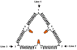
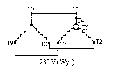
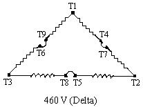
3 phase motor wiring diagram 12 leads whats wiring diagram. Typical wiring diagrams always use wiring diagram supplied on motor nameplate connection diagrams co4 460 12 leads part winding weg three phase motors 460 volts 12 lead part winding 12 10 11 645 789 12 3 l1 l2 12 10 11 64 5 78 9 12 l1 l2 12 10 11 64 5 789 123 l1 l2 starting type 460 volts across line starting type 460 volts soft.
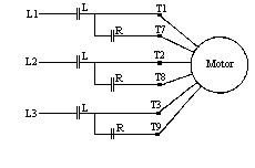
Part Winding
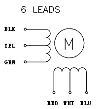
3 phase motor wiring diagram 9 leads. A wiring diagram is a form of schematic which uses abstract pictorial symbols to exhibit each of the interconnections of components inside a system. Randomly assign the numbers 789 to the 3 leads which are part of the 3 lead group. When a motors power supply is brought in from three wires instead of just one with the power delivery cycling through each of these in sequence hence the a part of ac it permits an effective power level that is 3 times higher about 1728 times higher than a. Capacitor motor single phase wiring diagrams always use wiring diagram supplied on motor nameplate. Wiring diagrams are made up of two things. Wiring diagram 6 lead 3 phase 480 volt motor wiring library 3 phase motor wiring diagram 6 wire wiring diagram contains the two examples 3 phase motor wiring diagram 12 leads june 15 2020 wiring diagram by anna r.
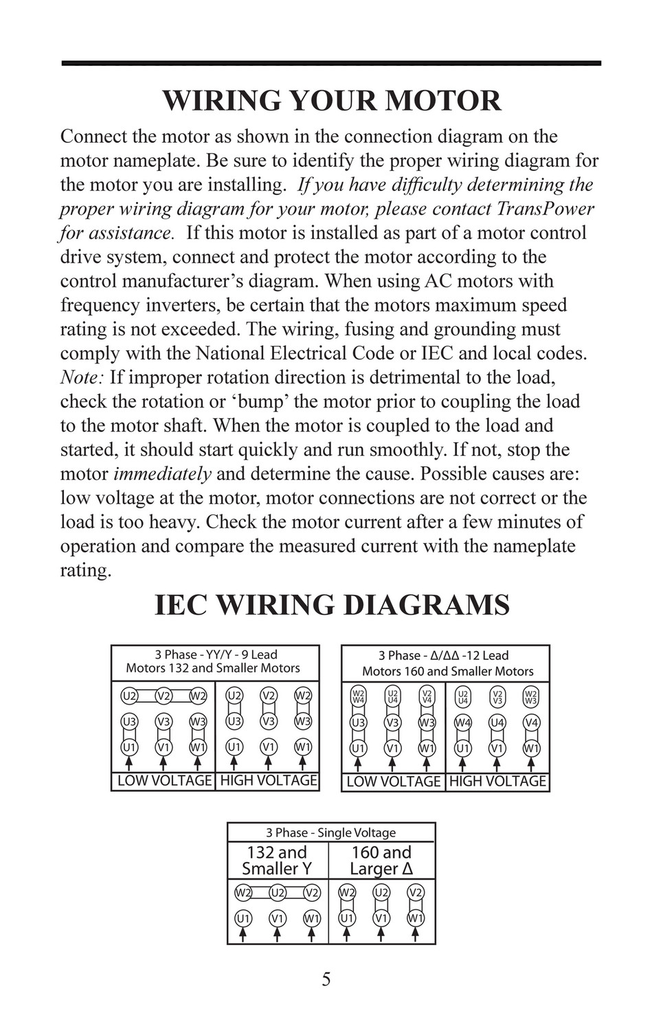
For specific leeson motor connections go to their website and input the leeson catalog in the review box you will find connection data dimensions name plate data etc. A three phase motor is more efficient than a single phase motor because of the peculiarities of alternating current ac. W2 cj2 ui vi wi w2 cj2 ui vi wi a cow voltage y high voltage z t4. Electric motor wire marking connections. On a 12 wire motor wired for high voltage ie 480v 10t 11t and 12t must be connected together but not connected to anything else. Symbols that represent the components in the circuit and lines that represent the.
Collection of 3 phase motor wiring diagram 9 leads. The other 9 wires would be connected as in a 9 wire motor note in a 9 wire motor the equivalent of t10 t11 and t12 are internally connected together. A wiring diagram is a streamlined conventional pictorial depiction of an electrical circuit. Always use wiring diagram supplied on motor nameplate colored leads are only applicable on the new rolled steel motor lines. You will be touching the battery between leads 8 and 9 polarity not important on this step and monitoring the voltage deflection on each of the other 3 pairs of wires each in succession. It shows the elements of the circuit as simplified shapes and the power as well as signal connections between the gadgets.
Three phase see below single voltage. Find the pair with the minimum or no voltage. L1 to t1 l2 to t2 l3 to t3 t4 to t7 t5 to t8 and t6.


