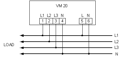
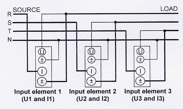
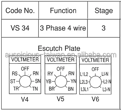
In the above diagram i shown 3 phase 4 wire system supply but i only connect l1 and l2 read and yellow to the volt meter or voltage meter. A toggle switch for switching on off the voltmeter 1 5.
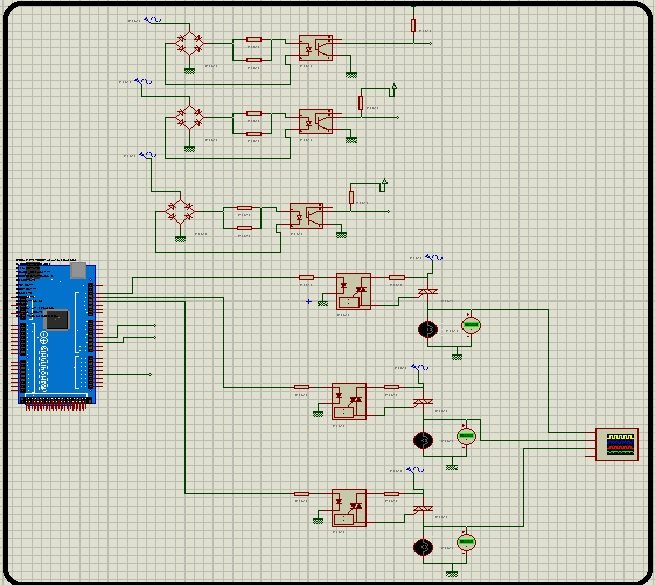
Soft Starter For 3 Phase Induction Motor Using Arduino
3 phase voltmeter connection diagram. In the above diagram i shown 3 phase 4 wire system supply but i only connect l1 and l2 read and yellow to the volt meter or voltage meter. In the united states for low voltage motors below 600v you can expect either 230v or 460v. The first step is to figure out the voltage of your phases. Phase indicator lamps ryb 3 6. Pls add indicator lights to each of the phases and show the wiring. I had to do this a few times with floodlights to be used outside.
In above digital 3 phase voltmeter connection diagram. Some length of flexible wire. A three phase motor must be wired based on the diagram on the faceplate. Electrical components such as 3 phase induction motor substation ac motors auto transformers ct instrument transformers pt instrument transformers dc motor dc generator elcb mcb no load. Pls show the connection diagram. For three phase voltage meter you can only connect 2 line wire and if you connect the neutral and phase to the voltmeter then volt meter show the 220 voltage which is single phase voltage.
The phasor diagram of the y connection of the three phase transformer is shown in the figure. The primary line voltage is equal to the secondary phase voltage. That being said there is a wide range of different motors and what you have on hand can be completely different. 0 230 v digital voltmeter 1 5. 63 amp rated 3 terminal connectors 2 4. I shown the neutral and phase supply goes to 6 and 8 terminals for voltage meter which is for operating the display.
Most of the components were purchased from local market. The y connection of the three winding transformer is shown in the figure below. As the l1 is connected to the 6 number terminal and this is also line than a wire connection will goes from this point to 2 number terminal. 3 phase motor contactor wiring diagram. The digital voltmeter was sourced from aliexpress. Start stop 3 wire control.
This will allow monitoring of which. In this video i guide complete about ammeter rotary switch and its. A complete guide of ammeter selector switch wiring diagram or rotary switch wiring diagram for 3 phase system load testing. For three phase voltage meter you can only connect 2 line wire and if you connect the neutral and phase to the voltmeter then volt meter show the 220 voltage which is single phase voltage. The relation between the secondary voltages is v ls 3 v ps. Below is the connection of 3 phase three phase or poly phase 3 phase4 wire kwh meter digital or analog energy meter from the supply to the main distribution board.
A simple circuit diagram of contactor with three phase motor. Starting a three phase motor. On abb contactor wiring diagram. 720 copper wire a few meters 7.
