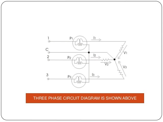
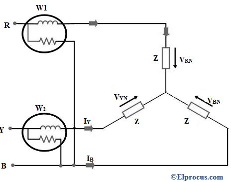
Three wattmeter method is used to measure power in 3 phase 4 wire circuits. Such as system is shown in fig.
Two Wattmeter Method Construction Derivation Amp Its
3 phase wattmeter connection diagram. In general m phase power can be measured by means of m 1 wattmeters. Three wattmeter method is employed to measure power in a 3 phase 4 wire system. Connection diagram to measure the three phase power with one wattmeter. The method is valid for both balanced and unbalanced circuits with either the load or the source unbalanced. In practice loads are not perfectly balanced and a fourth neutral wire is. 1 this only works as long as the voltages between themselves and the loads from the three phases are exactly the same.
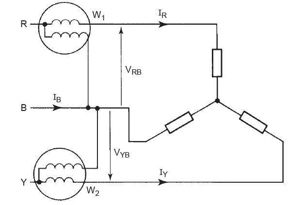
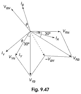
The circuit may be taken as balanced or unbalanced one balanced type being only a special case. This is known as the two wattmeter method of measuring three phase power. Wye or star connection a three phase system with a common connection is normally drawn as shown in figure 5 and is known as a wye or star connection. This point is often grounded at the supply for safety reasons. The circuit diagram is shown below here it is applied to three phase four wire systems current coil of all the three wattmeters marked as 1 2 and 3 are connected to respective phases marked as 1 2 and 3. However this method can also be used in 3 phase 3 wire delta connected load where power consumed by each load is required to be determined separately.
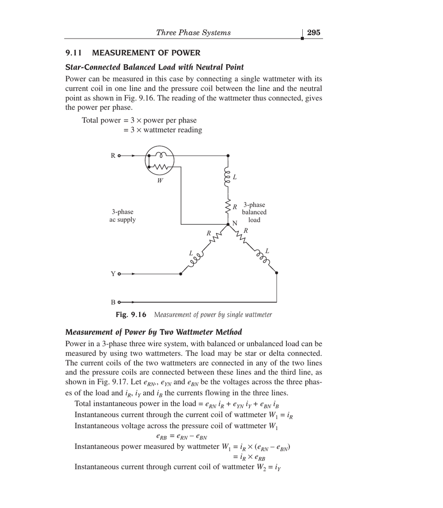
The connection diagram for the measurement of power in three phase power measurement circuit using two wattmeters method is shown in figure 1. This is irrespective of the circuit connection star or delta. This type of load is rarely found in practice because all the three wire star loads are balanced. Figure 431 shows the connection diagram for the two wattmeter method of measuring three. The current coil of both the wattmeter connects across any two phases say r and y. The pressure coil of both the wattmeters connects across the third phase say b.
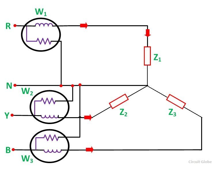
The mutual interference between the elements of the three phase wattmeter will affect their accuracy. By correct connection we mean the current coil must be connected in series and the pressure coil must be connected in parallel to the load whose power is to be measuredideally current coil and pressure coil have zero and infinite resistance respectively. Pressure coils of all the three wattmeters are connected to a common point at neutral line. However this method can also be employed in a 3 phase 3 wire delta connected load where power consumed by each load is required to be determined separately. It is very obvious to measure the power of only a single phase and to multiply this by three to become the total power of the installation. The figure below shows the three wattmeter connection of 3 phase 4 wire star connected load.
In a three phase four wire system if the connection between supply neutral and load neutral is broken it would result in an unbalanced three wire star load. The connections for star connected loads for. Consider the circuit has two wattmeters. Three wattmeter method of three phase power measurement. Therefore the current through the current coil of the wattmeter will be equal to load current and the voltage across the pressure coil of. The common point is called the neutral point.
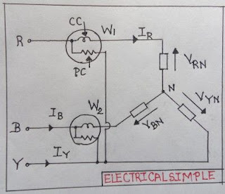
Connections of three phase wattmeter. Please not the connection of two wattmeters.
Gallery of 3 Phase Wattmeter Connection Diagram