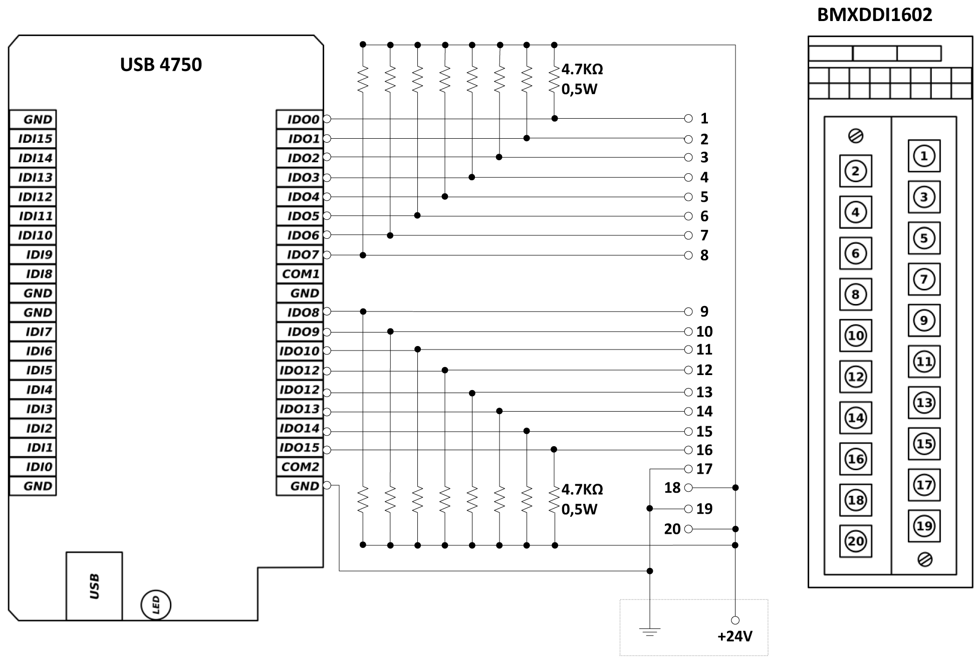
Before you start wiring any plc analog module i highly recommend that you not only read the manual but also know what type of signal youre dealing with. The internal schematic diagram for a discrete input module card shown above reveals the componentry typical for a single input channel on that card.

How To Wire A Proximity Sensor To A Plc
Plc input module wiring diagram. Input module interface receives the signal from process devices at 220 v ac. Isolator block is used to isolateprevent plc from undergoing fluctuation. There the signal and neutral are paired and passed to the plc module. Note that the return neutral wire labeled 02n since it is the return wire for cb2 is split to the plc and the. Check module type and model number by inspection and on the io wiring diagram. The following are ten recommended procedures for io wiring.
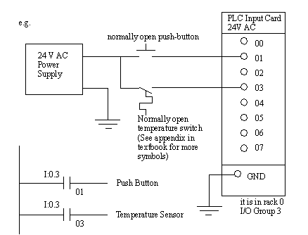
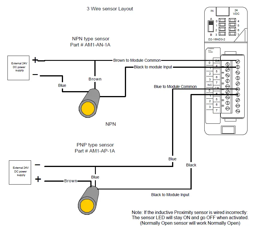
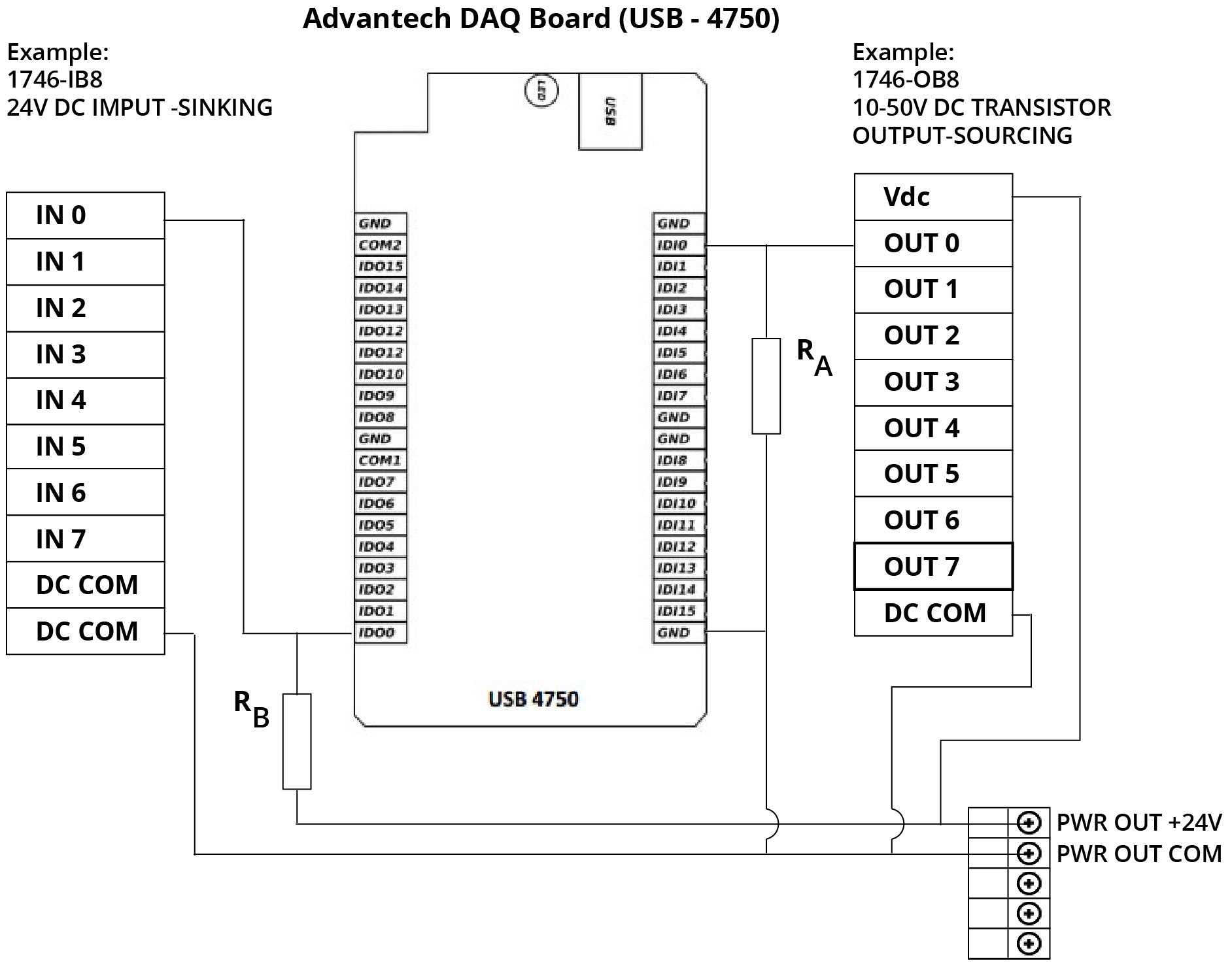
Below are detailed electrical diagrams for sinking and sourcing configurations showing typical plc input module and field device circuitry. Wiring a plc analog input is a bit different depending on the type of signal. After which the signal is sent to the output end ie the plc. Common terminals and how to use them in order for a plc io circuit to operate current must enter at one terminal and exit at another. In this tutorial i will cover wiring of the two most basic analog input signals. Remove and lock out input power from the controller and io before any plc installation and wiring begins.
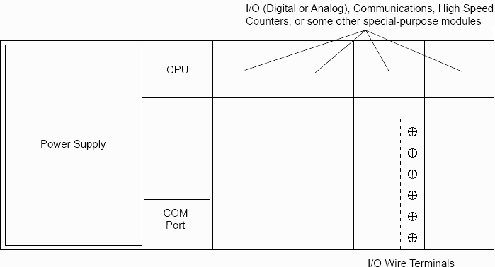
Plc wiring diagrams guide include the discrete signals wiring plc digital input modules wiring plc output modules wiring and basics of plc terminations. Verify that all modules are in the correct slots. Converts the input signal to 5 v dc that can be used by plc. Each input channel has its own optocoupler writing to its own unique memory register bit inside the plcs memory. The input module of plc does four main functions.
