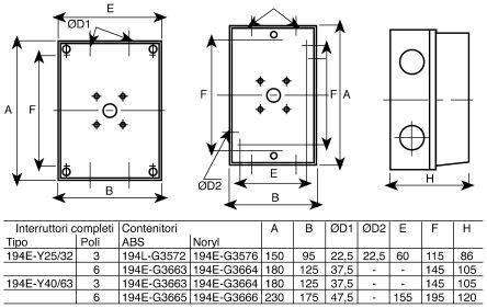
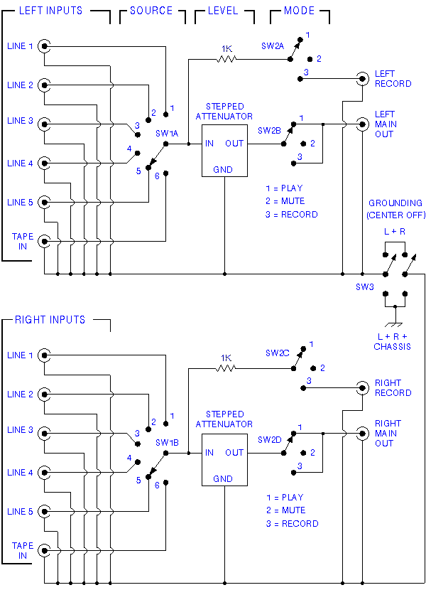
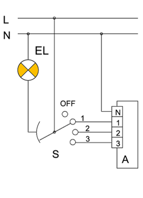
Switch off the mains supply before. Connect the new socket or switch as shown in the appropriate wiring diagram in these fitting instructions taking care that only the copper conductors enter the terminals.
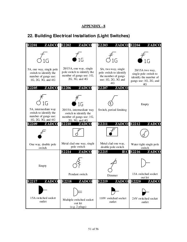
Iec Symbol Reference
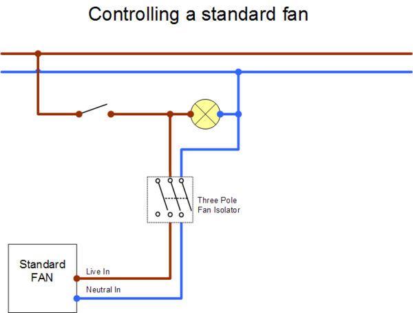
3 pole isolator switch wiring diagram. It shows the components of the circuit as simplified shapes and the knack and signal associates in the middle of the devices. For guidance see the current edition of the iee wiring regulations bs 7671. It must be out of reach of any person using the bath or shower. Wiring a 3 way light switch. To prevent electrocution do not work on any appliance live. 3 pole fan isolator switch wiring diagram wiring diagram is a simplified standard pictorial representation of an electrical circuit.
Ammeter switches with 0. I explain the wiring using basic wiring. Lap 10a 1 gang 3 pole fan isolator switch brushed stainless steel with colour matched inserts 37411 product. Wiring a 3 way light switch is certainly more complicated than that of the more common single pole switch but you can figure it out if you follow our 3 way switch wiring diagram. In this video i show how to wire a 3 pole fan isolator switch for a timer fan using 3 core earth cable and for a non timer fan using twin earth cable. It is absolutely vital that the terminal screws do not clamp on the insulation of the cables.
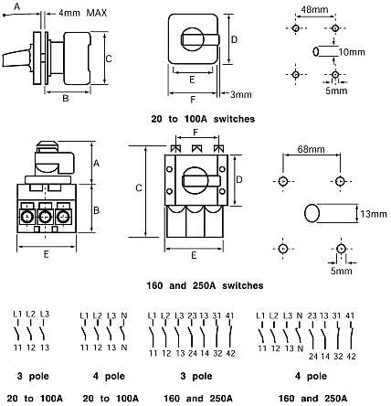
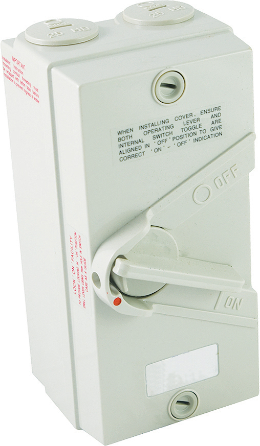
Voltmeter and ammeter selector switches. With a pair of 3 way switches either can make or break the connection that completes the circuit to the light. Fan isolator switches 50 products a fan isolator switch is normally used with an extractor fan to enable isolation of the fan for repair and maintenance and is fitted outside the room. Cam operated rotary switches used to perform make and break the cam switches offers versatile mounting options in addition to standard. The 3 pole fan isolator can be installed in bathrooms but only under the strictest of conditions. Pole change switches and reversing pole change switches page 363.

