However this would not be a good solution for non separately derived systems. Electricalonline4u a platform to learn electrical wiring single phase 3 phase wiring controlling hvac electrical installation electrical diagrams.

Transfer Switch Mccb Type 1000amp 1200amp
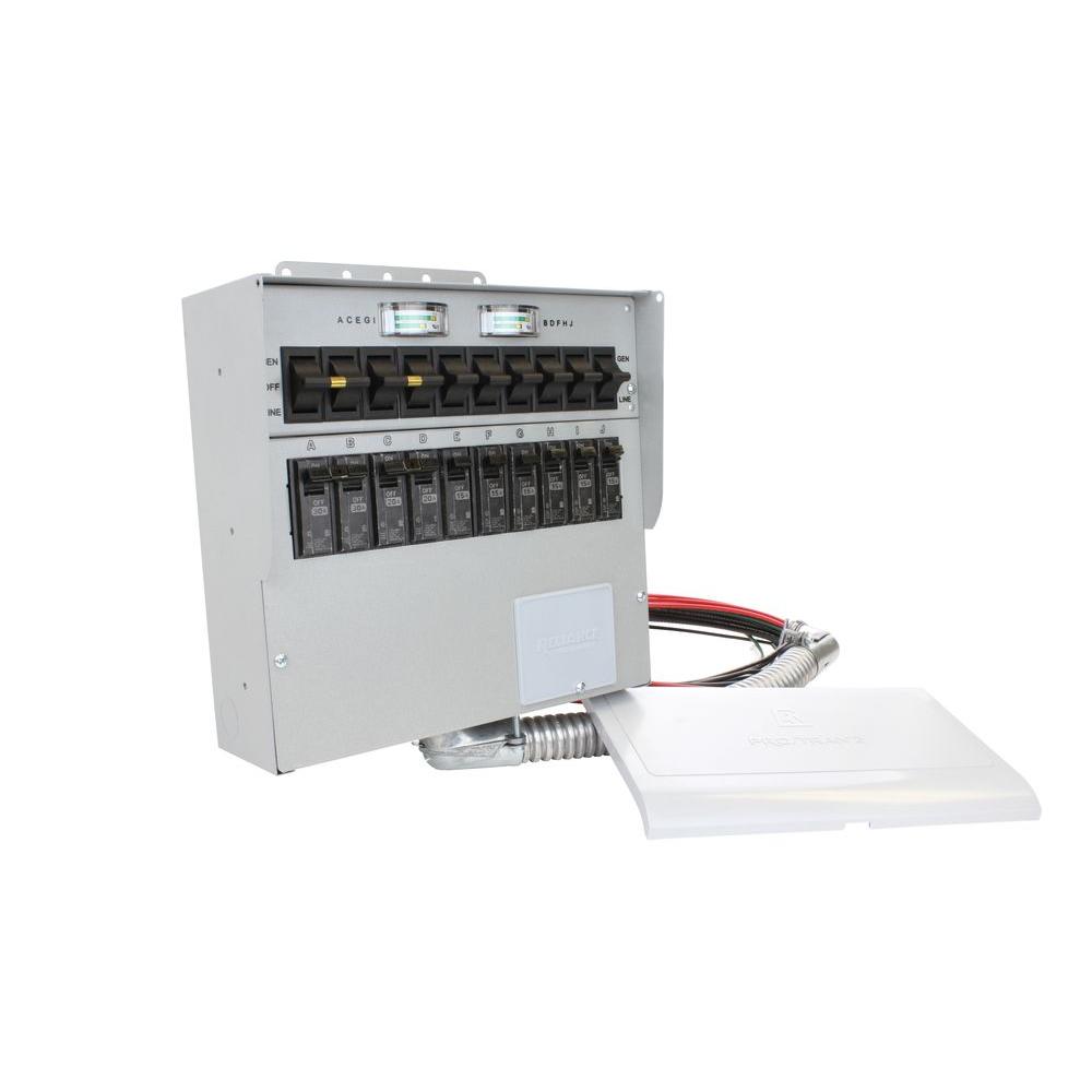
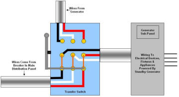
3 pole transfer switch wiring diagram. In its most basic form a transfer switch for a 120240v single phase service is simply a double pole double throw switch of proper ampere rating with a middle off position fig. Assortment of 3 pole transfer switch wiring diagram. They should join the circuit breaker through a knockout found at the bottom of the box. It is also shows the working and operation for different changeover switches wiring connections like single phase manual changeover switch with generator three phase manual transfer switch connection with generator as well as single phase and three phase automatic transfer switches connections to the 1 and 3 phase generators and main fuse board. Match your critical circuits with circuit inlet on your pre wired transfer switch. The wires should be drawn through 1 of 3 knockouts located on the underside of the switch.
Manual changeover switch wiring diagram for portable generator or how to connect a generator to house wiring with changeover transfer switch. A second solution would be to use a transfer switch that switches the neutral. Use the transfer switchs wiring harness to connect the unit to the circuit breaker. If a 4 pole device was used the load would be ungrounded when connected to an ungrounded source. Because there is now a 3 pole ats in this system the neutral is continuous and the generator is not considered to be a separately derived source. Double pole 240 volt circuits will require two 120 volt circuit connections.
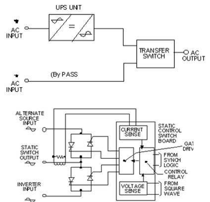
It reveals the parts of the circuit as streamlined shapes and the power and signal links between the gadgets. Collection of 3 pole transfer switch wiring diagram. By design it is a physical impossibility for both power sources to supply the load simultaneously unless of course that is the intent. Try to balance the load as best you can in the transfer switch. There is no neutral to ground link at the generator. A wiring diagram is a simplified traditional photographic depiction of an electric circuit.
A wiring diagram is a simplified conventional photographic depiction of an electric circuit. This is essential to. If a line to ground fault were to occur while the. Selecting between a three pole or four pole ats 5 final thoughts while there are many factors that determine whether to use a three or four pole transfer switch it should be emphasized that in systems with more than one ats it is important to use the same ats configuration three or four pole throughout the system. Using a 3 pole transfer switch next consider adding a 3 pole ats and a generator to the aforementioned simple circuit see figure 3. Sources in this case sources 2 and 3.
It shows the parts of the circuit as simplified forms and also the power and also signal links in between the gadgets. For example if your refrigerator is on the leftmost switch circuit connect your freezer to the circuit farthest to the right.


