This is the wiring for a dimmer in a 4 way circuit. To use a dpdt relay as a 4 way switch the normally open no contact of pole one would be wired to the normally closed nc contact of pole two.

How To Wire A Relay For Off Road Led Lights Extreme Lights
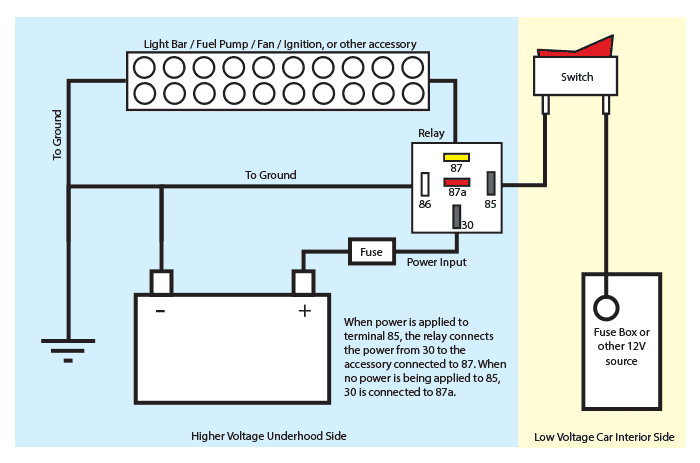
4 way relay diagram. To make this circuit work a 3 way dimmer can be used in place of one or both of the standard 3 way switches. You will find excellent wiring diagrams for all makes years and models of vws at vw wiring diagrams. If the coil is not activated 30 will always be connected to 87a. This way id be sure the right circuitsfuses. In this video i show you how to wire a 12 volt automotive bosch style relay. The first and last switches in the line would be 3 way switches and as many additional switches as needed in between would be 4 way switches.
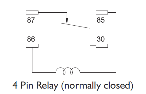
The relay in turn powered both left and right front indicators from a separate fuse source. 85 and 86 are the coil pins while 30 87 and 87a are the contact pins. The white wire of the cable going to the switch is attached to the black line in the fixture box using a wirenut. The switch connected both rear lights to the flasher and simultaneously connected a relay to the flasher. How to test a relay the easy way duration. How to test a 3 4 or 5 pin relay with or without a diagram duration.
Three wire cable runs between all the switches and 2 wire cable runs to the light. Hii am having difficulties to replace my current switches. Numbers of a relay. The white wire becomes the energized switch leg as indicated by. Ratchets and wrenches 1038409 views. This 4 way switch diagram 1 shows the power source starting at the left 3 way switch.
Note that each pin is numbered. This video covers both 4 and 5 pin 12vdc relays. 4 way switch wiring diagram australia. For example a low power circuit in a car that commands the high power headlights to come on would send the command through a 4 terminal relay. 87 and 87a are the two contacts to which 30 will connect. This 4 way switch diagram 2 shows the power source starting at the fixture.
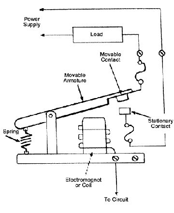
4 way dimmer switch wiring diagram. Early bus hazard wiring 62 thru 65 models used a switch and a relay to provide 4 way flashing hazard lights. Looking at the diagram we see the pinout of a typical 12v relay. A 4 terminal relay is used so a low power circuit may engage a high power circuit without risk of damage to the low power control circuit.


/hon_mnrelay_tst-56a0556e5f9b58eba4afeb33.gif)


