Terminals 3 and 4 represent the toggle switch. How to wire a on off on toggle switch diagram.

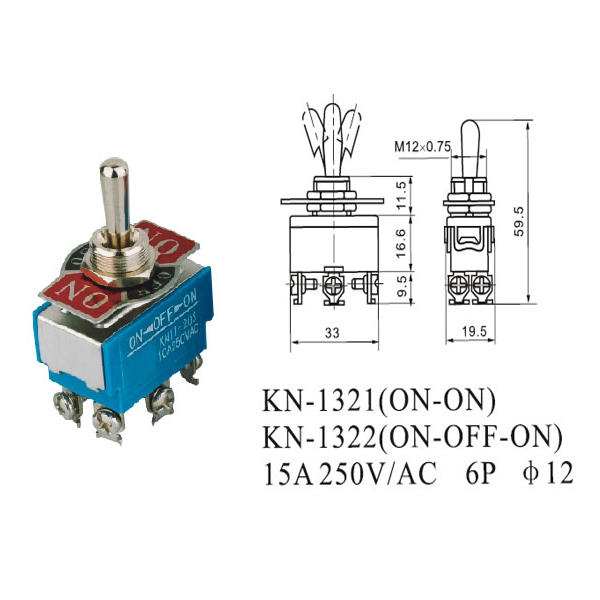
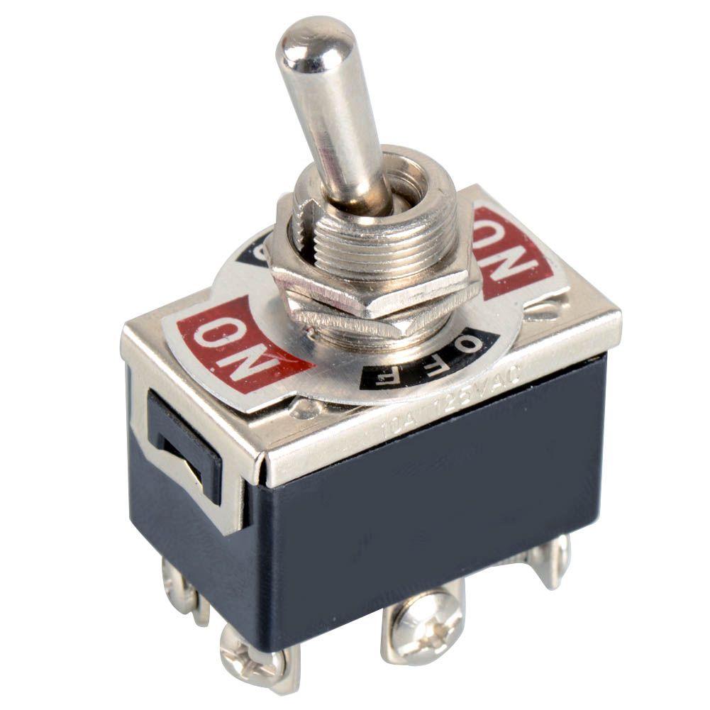
Metal Toggle Switch 6 Pin Dpdt On Off On
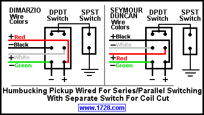
6 pin toggle switch wiring diagram. Collection of 6 pin dpdt switch wiring diagram. Here is a diagram of a spdt toggle switch. Collection of 6 pin toggle switch wiring diagram. The term double pole generally means that two pinsterminals exist for each connection point. We will now go over the wiring diagram of a dpdt toggle switch. It shows the elements of the circuit as simplified shapes and also the power and signal connections in between the gadgets.
Quentacy 19mm 3 4 metal latching pushbutton switch 12v buy quentacy 19mm 3 4 metal latching pushbutton switch 12v power symbol led 1no1nc spdt on off black waterproof toggle switch with wire socket plug blue how to wire a 3 way switch wiring diagram how to wire 3 way light switches with wiring diagrams for different methods of installing the wire. It makes one of two connections. A wiring diagram is a streamlined conventional photographic depiction of an electrical circuit. When wiring this switch you can choose if youd like to illuminate it because of the independent lamp attached to terminals 8 and 7. A spdt is a bit more sophisticated. A six pin toggle switch is also called a double pole double throw or dpdt switch.
Terminal 2 is connected to power. If you want to connect two dc motor only change the common polarity connection into two part and make connection seperately. A dpdt toggle switch has 6 terminals. Variety of 6 pin toggle switch wiring diagram. Thanks for a2ayou can easily under stand by the schematic picture shown below believe me it will work 100. Spdt toggle switch single position dual throw xx.
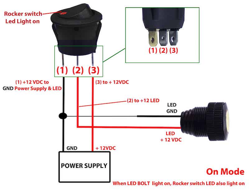
It shows the elements of the circuit as streamlined forms and the power as well as signal links in between the gadgets. Or these terminals can be ignored for non backlit switch banks. In this video we are giving a tutorial on how to wire a rocker switch with led 6 and 7 pin wiring diagrams to control a linear actuator as well as showing how exactly a rocker switch works. It shows the parts of the circuit as streamlined forms as well as the power as well as signal connections in between the devices. A wiring diagram is a simplified standard pictorial representation of an electrical circuit. The term double throw means that you can connect two separate devices and each switch position selects one of the two devices.
Terminal 1 is connected to one load or accessory terminal 3 is connected to another load or accessory. A wiring diagram is a streamlined conventional pictorial depiction of an electric circuit. Below is the schematic diagram of the wiring for connecting a dpdt toggle switch. The wiring diagram to the right will show how to wire and power this 12v 20amp on off on 3 way carling contura rocker switch. These terminals receive the power necessary to drive the loads on terminals 1 and 5 and 2 and 6.


