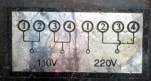
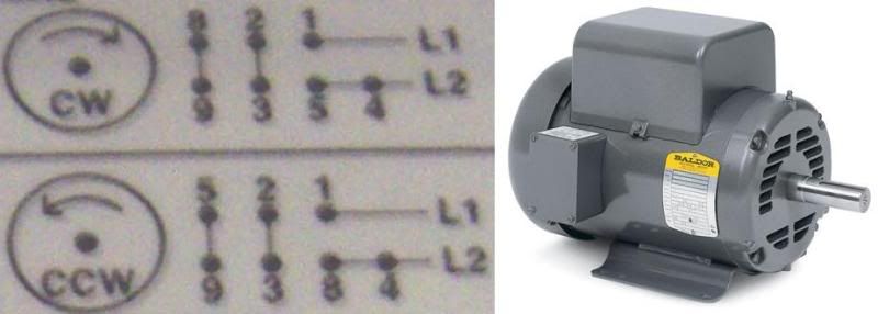
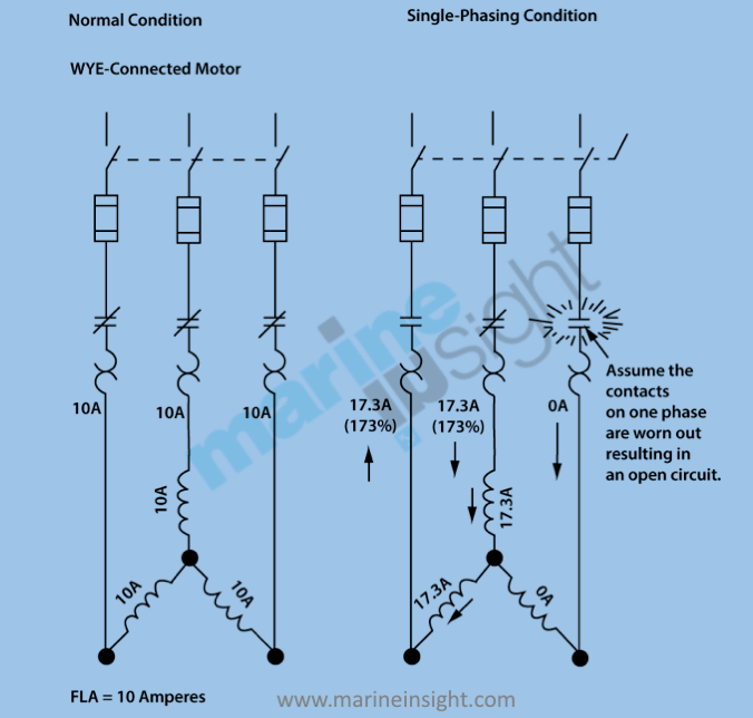
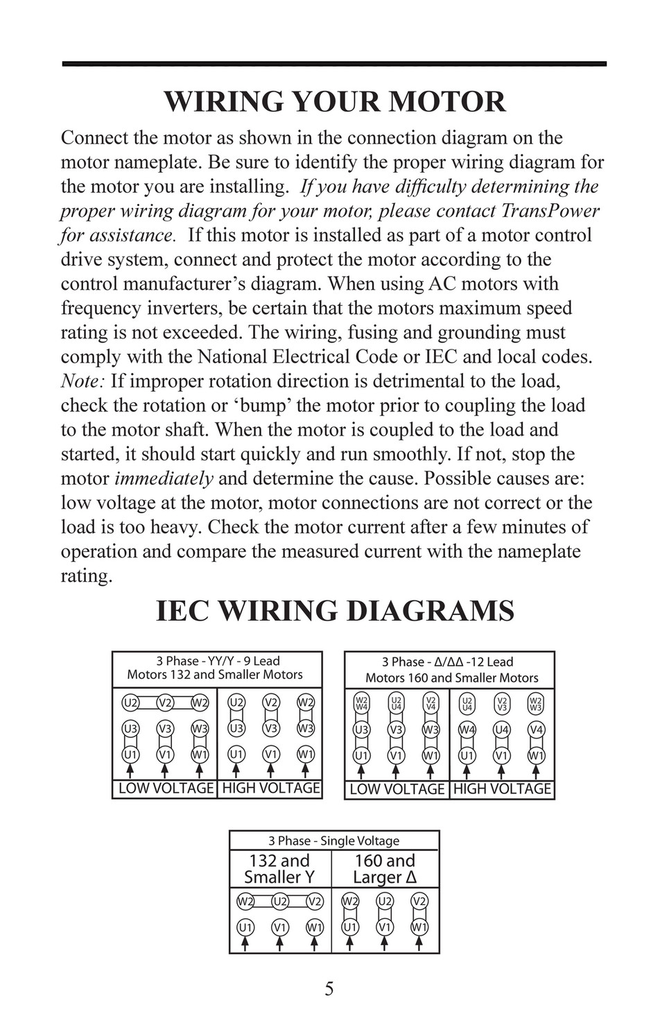
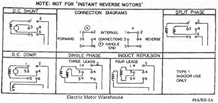
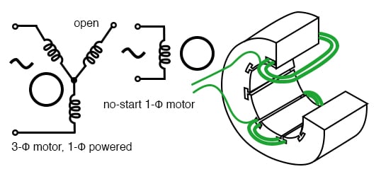
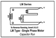
Wiring diagram for single phase motor fresh pretty single phase. These tips can be used on most electric motor brands such as weg baldor.

3phconv
7 lead single phase motor wiring diagram. Learn how a capacitor start induction run motor is capable of producing twice as much torque of a split phase motor. A motor with a start and run capacitor and a start and run coil. Capacitor motor single phase wiring diagrams always use wiring diagram supplied on motor nameplate. It shows the elements of the circuit as streamlined shapes as well as the power and signal links in between the tools. Also read about the speed torque characteristics of these motors along with its different types. Residential power is usually in the form of 110 to 120 volts or 220 to 240 volts.
Baldor motor capacitor wiring diagram a novice s overview of circuit diagrams. Wondering how a capacitor can be used to start a single phase motor. W2 cj2 ui vi wi w2 cj2 ui vi wi a cow voltage y high voltage z t4 til t12. A wiring diagram is a streamlined traditional photographic depiction of an electrical circuit. In this video jamie shows you how to read a wiring diagram and the basics of hooking up an electric air compressor motor. If a single phase motor is single voltage or if either winding is intended for only one voltage the terminal marking shall be determined as follows.
Click here to view a capacitor start motor circuit diagram for starting a single phase motor. Terminal markings and internal wiring diagrams single phase and polyphase motors meeting nema standards b. This video will show you how to connect a single phase motor with two capacitors. With single phase motor with capacitor forward and reverse wiring. Single phase motors are used to power everything from fans to shop tools to air conditioners. In such case each cable will be marked with the appropriate lead number.
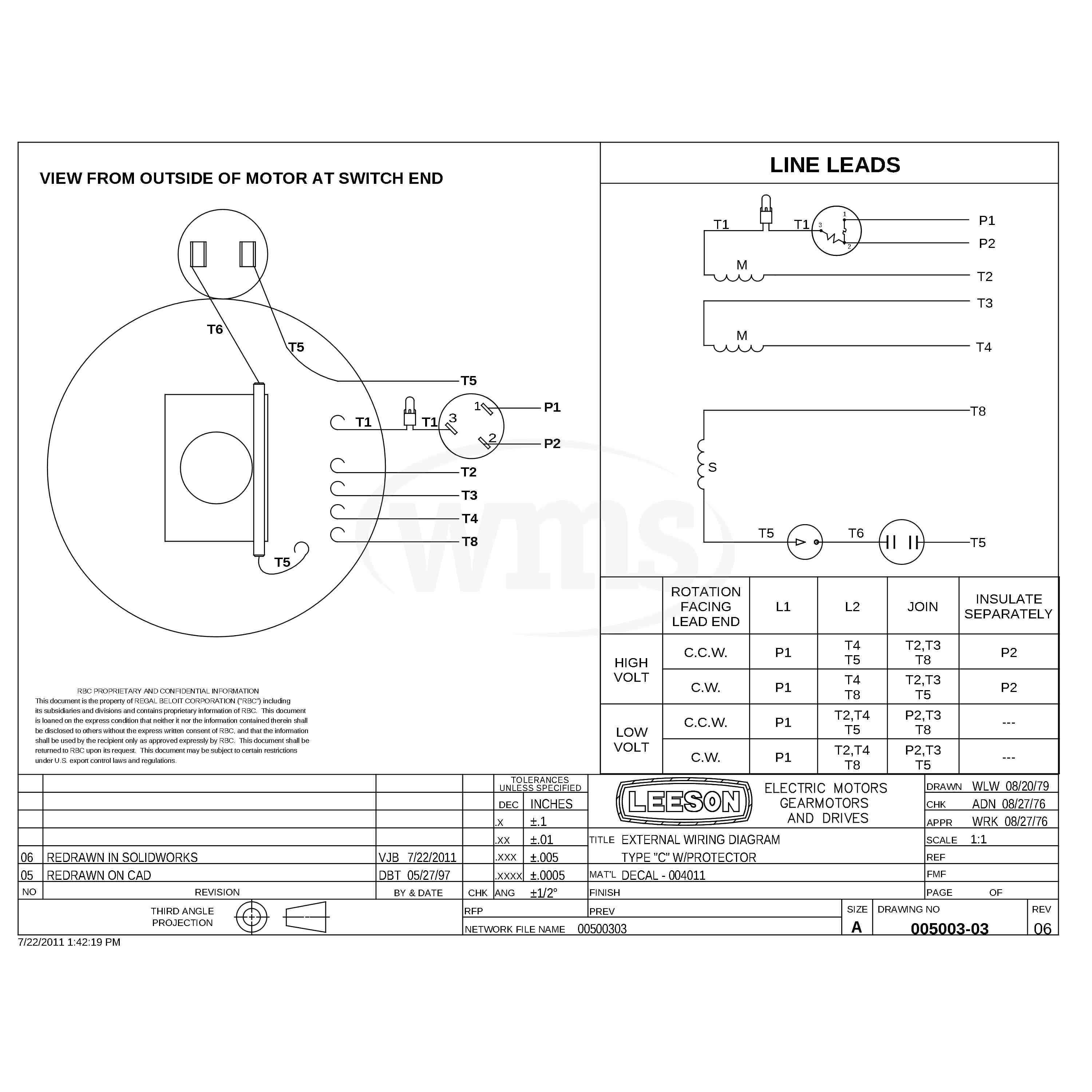
Single phase motor wiring diagram with capacitor sources. Always use wiring diagram supplied on motor nameplate for motors with thermal protection single voltage single rotation single voltage reversible rotation. Single phase motor wiring diagram forward reverse collections of phase meter wiring diagram single phase motor capacitor wiring. Collection of baldor single phase motor wiring diagram. Motor wiring diagram 904983 7 lead dual voltage 115 230 single phase with thermal protection clockwise rotation facing shaft as shown interchange leads t5 t8 for counter clockwise rotation each lead may have one or more cables comprising that lead. Wiring a motor for 230 volts is the same as wiring for 220 or 240 volts.
A very first take a look at a circuit representation may be complicated however if you can read a metro map you could review schematics.

