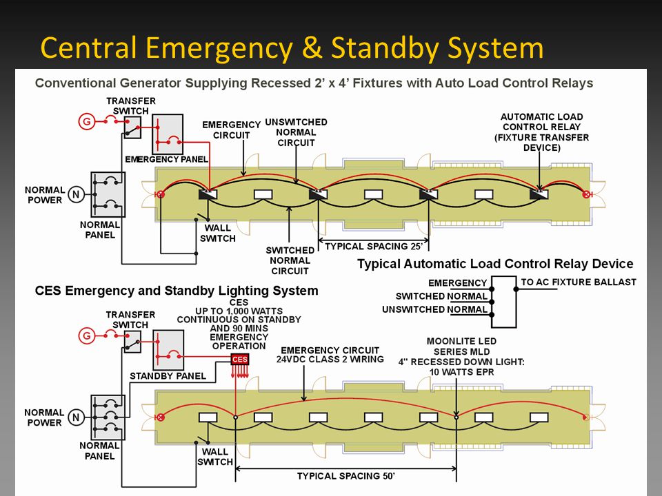
Central inverter basics 2. Typical wiring diagrams emergency lighting wiring diagrams when using a central inverter this document provides fully compliant 2017 nfpa 70 nec article 700 wiring diagrams using a central emergency lighting inverter and ul924 approved emergency lighting control device elcd.

Wiring Diagram
Central lighting inverter wiring diagram. Benefits of inverters 3. 2 summary generalpresentation page12 singlephasecompactsystems page34 singlephaseinterruptiblesystems page56 singlephasefasttransfersystems page78. Central lighting inverter wiring diagram wiring diagram is a simplified pleasing pictorial representation of an electrical circuit. Central inverter basics lighting inverters ensure uninterrupted power to devices in times of power outages. It shows the components of the circuit as simplified shapes and the skill and signal connections in the middle of the devices. What are the cost savings.
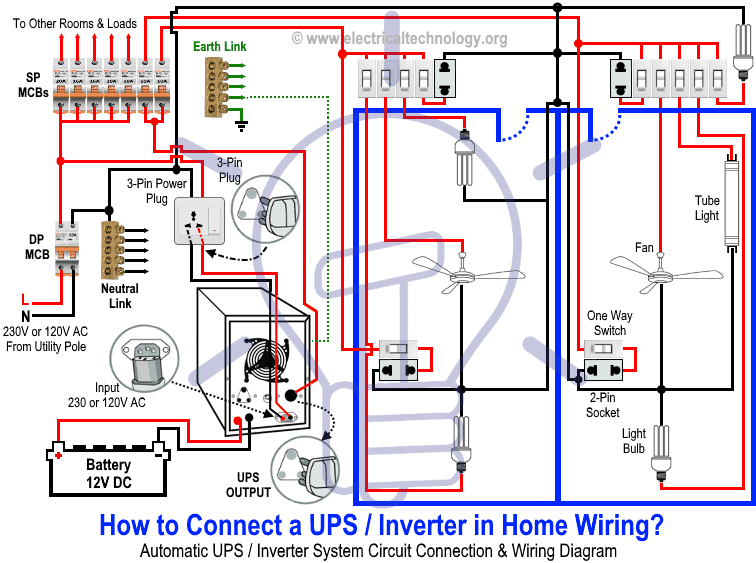
Typical wiring diagram emergency lighting mini central inverter system black white blue white brown black switched command signal violet earth ground green input wiring line switched output neutral normally on normally off output wiring neutral light fixtures led hid incandescent or fluorescent cap off unused wires diagram 1. Wiring schematics and load calculations explained 4. Installation users guide nema 3r outdoor emergency lighting central inverter 3kw 8kw single phase 4kw 8kw three phase 44 south commerce way bethlehem pa 18017 1 800 526 5088 610 868 3500 fax. Common terms for inverter schematics 6. Diagrams show single zone.


