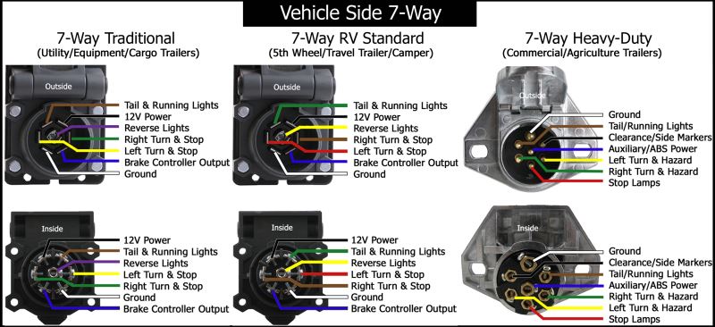
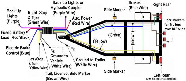
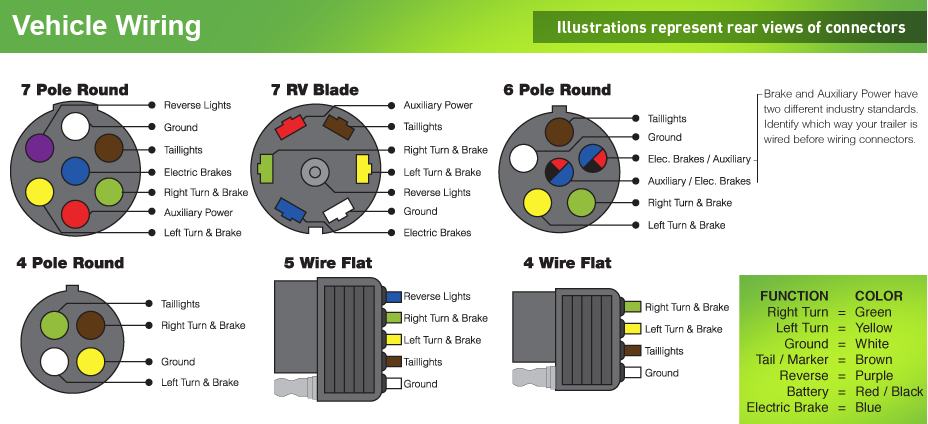
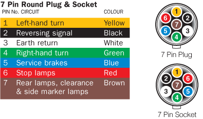
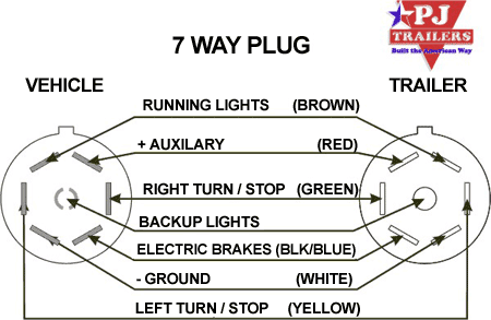
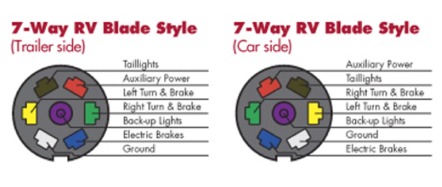
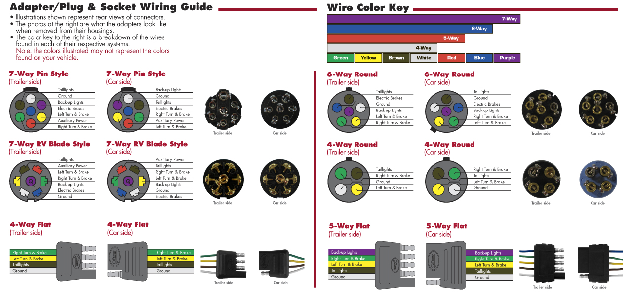
7 pin trailer wiring diagram with brakes 7 pin flat trailer wiring diagram with brakes 7 pin rv trailer wiring diagram with brakes 7 pin trailer wiring diagram with brakes every electrical arrangement is made up of various different parts. Looking at the 7 way from the outside front it will be at the 500 position.

Bargam 7 Way Wiring Diagram Hitches Anderson Curt Friess
7 pin trailer plug wiring with electric brakes. They also provide a wire for a ground connection. Trailer wiring diagrams trailer wiring connectors. Auxiliary power is supplied by compatible vehicles through a 7 pin 12 pin or anderson plug with at least a 30 amp rating. As the name implies they use four wires to carry out the vital lighting functions. Use the 7 pin connector anyway see below and just leave out the last 2 wires. You will want to make sure that the prodigy brake controller you have is designed for electric over hydraulic brakes.
This would remove the need to keep the tow vehicles headlights on while elecbrakes is in use. 4 way trailer connectors are. An auxiliary circuit can also be used on a single or double axle trailer. Trailer plug wiring diagram 4 pin duration. This short video is about trailer brakes electric brakes and wiring. If your truck has a built in 7 pin socket but you only need 5 of the pins.
7 pin trailer wiring is one of the most popular wiring configruations particularly the traditional configuration versus the sae j2863. If not the arrangement will not function as it ought to be. The wiring installation is the same on all of the of the brake controllers. The four wires control the turn signals brake lights and taillights or running lights. Thanks for watching. 7 way plug wiring diagram standard wiring post purpose wire color tm park light green battery feed black rt right turnbrake light brown lt left turnbrake light red s trailer electric brakes blue gd ground white a accessory yellow this is the most common standard wiring scheme for rv plugs and the one used by major auto manufacturers today.
Each component ought to be set and connected with different parts in particular manner. Blue electric brakes or hydraulic reverse disable see blue wire notes below in the trailer wiring diagram and connector application chart below use the first 5 pins and ignore the rest. It also talks about electric brake controller. Various connectors are available from four to seven pins that allow for the transfer of power for the lighting as well as auxiliary functions such as an electric trailer brake controller backup lights or a 12v power supply for a winch or interior trailer lights. I am including a picture of a 7 way and it shows the functions of each pin. Use this 7 pin trailer wiring diagram to properly wire your 7 pin trailer plug.
4 way trailer connectors are typically used on small trailers such as boat snowmobile utility and other trailers that that do not use brakes.
