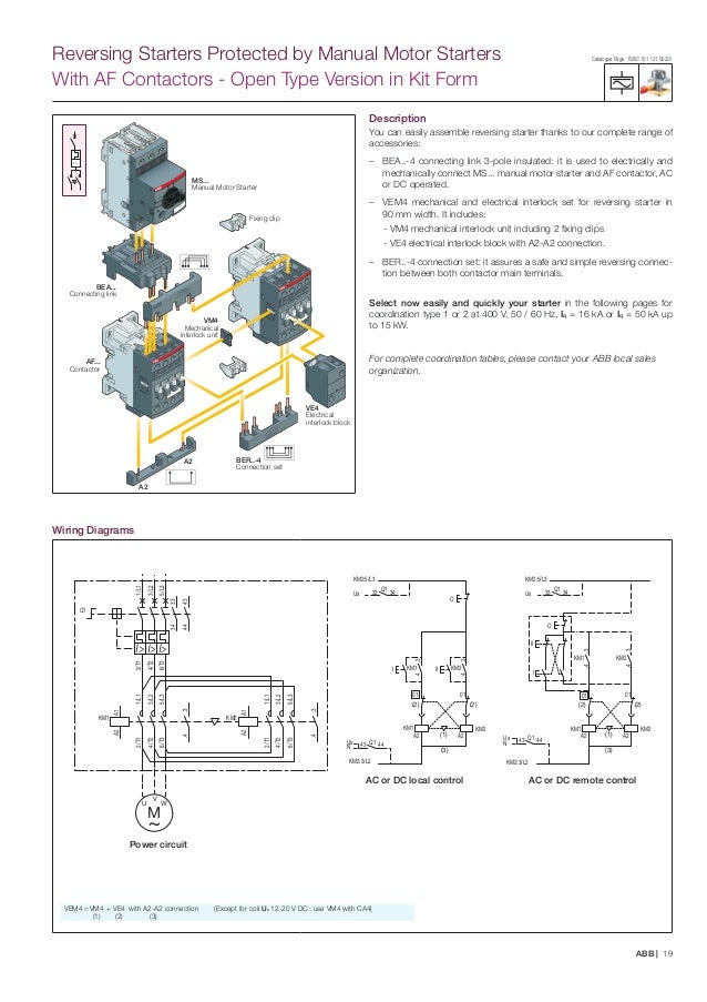
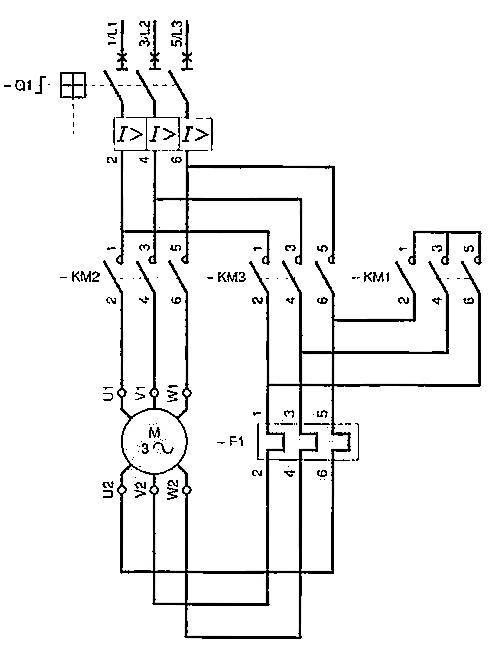
66 412 connection diagram 68 5. Abb mns30 product presentation 03 2012.

Wz 9391 Abb Vfd Control Wiring Diagram Free Download
Abb motor connection diagram. It reveals the components of the circuit as simplified forms and also the power as well as signal connections in between the gadgets. Six swiss ex is a leading global technology company that energizes the transformation of society and industry to achieve a more productive sustainable future. Collection of abb vfd wiring diagram. A wiring diagram is a streamlined traditional pictorial representation of an electrical circuit. Abb library is a web tool for searching for documents related to abb products and services. By connecting software to its electrification robotics automation and motion portfolio abb pushes the boundaries of technology to drive performance to new levels.
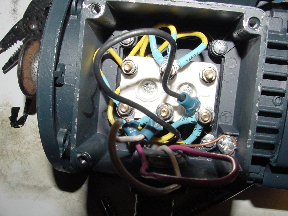
Iec low voltage ac motors. M prusi approved by. Upgrade from insum 1 2 projects utilizing abb motor controller m10x m101 m102. Abb library is a web tool for searching for documents related to abb products and services. Mechanical design 69 51 motor construction 70 52 frame constructions 71 53 terminal boxes 73 54 bearings 74 55 drain holes and humidity 75 56 external radial and axial forces of the motor 75 57 balancing 76 58 vibration 77 59 surface treatment 80 6. Thermal contacts tb white m 1 z2 yellow z1 blue u2 black u1 red bridge l1 and l2 if speed controller sc is not required m 1 ln e.
Abb motors customer reference. Abb motors oy mso date. 3 phase squirrel cage two speed motor unit. Direction of rotation with phase sequence shown in picture drehrichtung nach schaltbild. Diagram dd6 diagram dd7 m 1 ln e diagram dd8 ln e l1 l2 l3 sc z1 u2 z2 u1 cap. Connection diagram document no.
Auxiliary connection diagram variant code 450 motor sizes 80 280 pu fimot. Customer further acknowledges that abb makes no warranty with respect to such information and customer shall not rely on abb for the accuracy or completeness of information supplied through such software or services. Customer accepts all such information on an as is as available basis. 8 introduction to the manual contents of the manual the manual tells about the grounding and cabling principles of variable speed drive systems and gives examples for correct cabling and grounding practices. Diagram dd5 two speed motors for all other single phase wiring diagrams refer to the manufacturers data on the motor.



.png)
