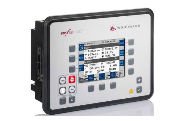
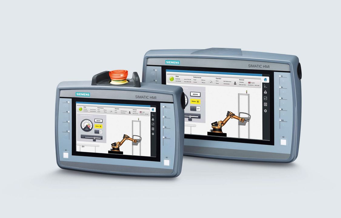
Powerwizard20 replaces the 4001e access 4000 and 6100 control panels and is used for applications where comprehensive monitoring and protection andor remote monitoring and control is required. When communication via lan the pcb is referred to as an iq400e page iii of 110 iq 400 installation manual 33 10057 001 c.
Asco 7000 Series Power Transfer Switch Asco Power Technologies
Access 4000 control panel wiring diagram. Le4000 wiring diagrams le4000 installation manual section 8. Repair access 4000 olympian and fg wilson generator control circuit board autostart. The panel provides enhanced ac metering including kw kva kvar power factor kwh kvarh in addition to voltage amps and frequency metering. To phrase it in a popular way you can say that there are 10 things you need to know in order to draw a wiring or power control circuit diagram quickly and effectively in pcschematic automation. How to place symbols. Repair time repair process standard warranty wiring schematics payment options.
Microprocessor controlled access 4000 control panel. Wiring the remote control is an optional accessory that al schematicdiagram can be used to help follow the lows the genset to be started monitored and circuit description. Le4000 wiring diagrams figure 8 1 le4000 wiring diagram. The first thing you need to know is how to place symbols in a diagram page in the software. Optional remote control a2 a3 control operation the schematic diagrams in section 12. 01 board diagrams 011 the iq 400 printed circuit board wiring diagram note.
Pgm2 on the le4000 must be set as active control panel. Always refer to the specific wir stopped from a remote location. Page 23 when the radio is powered by the control panel the relay is not required since a loss of input power will generate a signal to the cmc.


