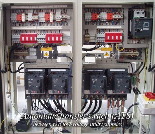
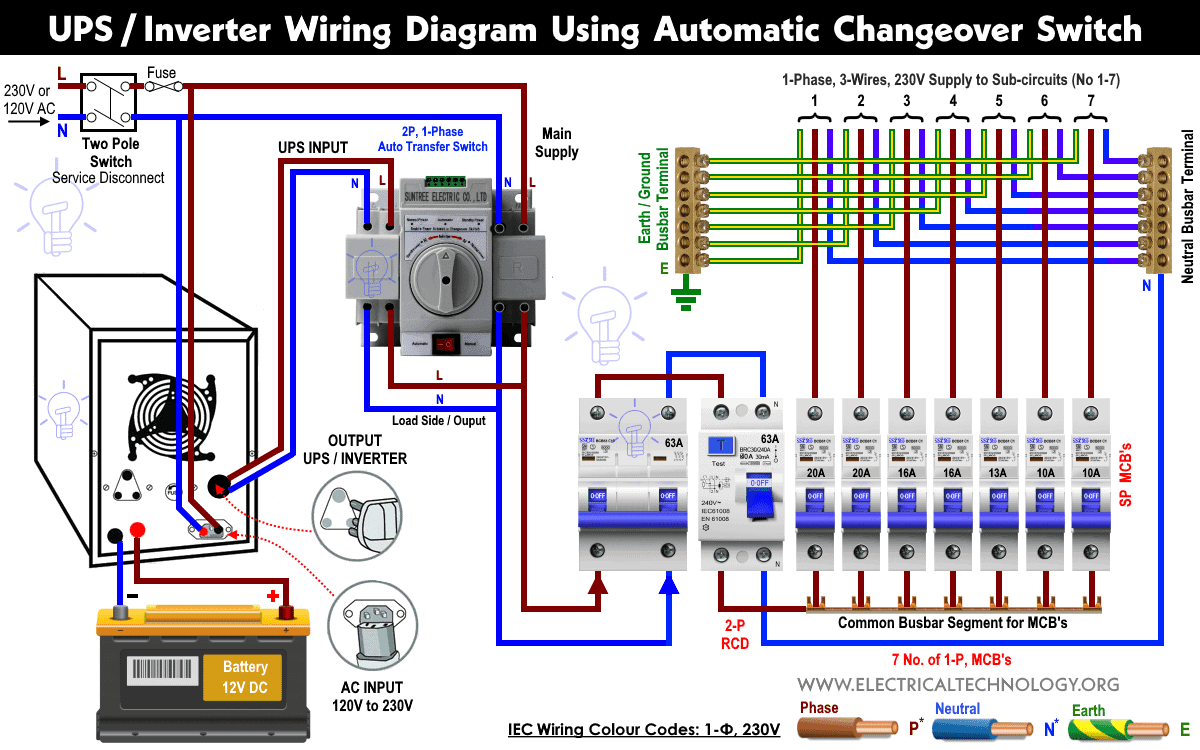
The main source branch cb protection coming either from generator or line has to be turn off. Ats gts schematic diagram servicing the ups ats.

Xk 1164 Board Circuit Diagram Electricalequipmentcircuit
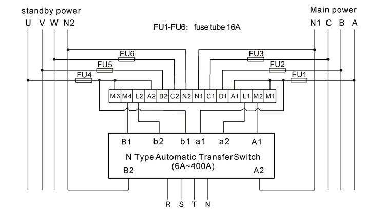
Ats schematic circuit diagram. 15 schematic circuit diagram for automatic transfer switch 16 recommended cable size 17 specifications 171 general specification. Ats and gts combine. Automatic transfer switch diagram. Turn off cb1 sw1 and battery cb of. This manual should remain with the unit. So far i know if there is a voltage coming from normal supply via q611 a coil k1 will energised and the voltage will come to x211 on ats.
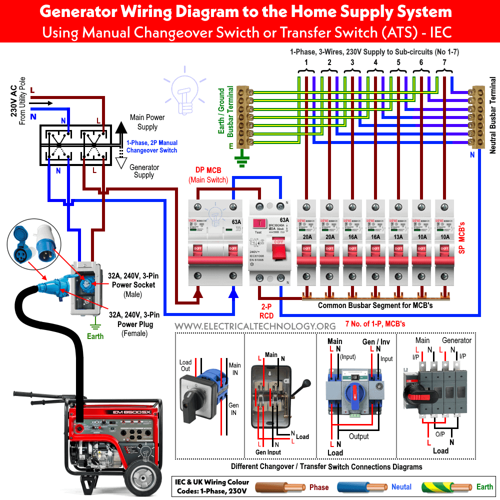
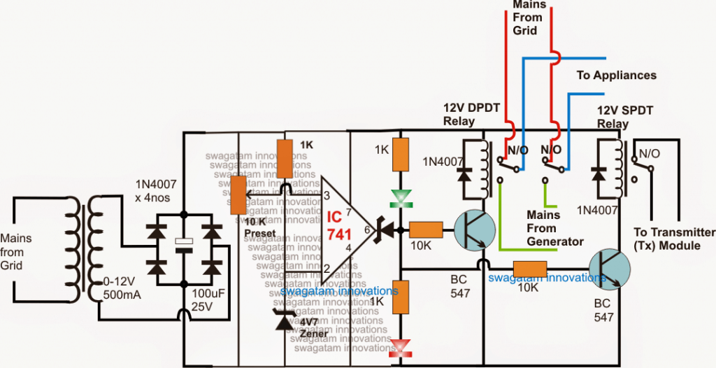
A distribution board also known as panelboard breaker panel or electric panel is a component of an electricity supply system that divides an electrical power feed into subsidiary circuits while providing a protective fuse or circuit breaker for each circuit in a common enclosure. Ats panel for generator wiring diagram pdf data wiring diagram. If some conditions are fullfiled d01 and d02 will close and yc of cb1 n if. Updated ats circuit diagram with complete ic 4060 and ic 555 wiring details design2 the following article explains an enhanced automatic transfer switch ats circuit which includes several customized sequential changeover relay stages making the system truly smart. Technical information 3 standard diagrams transfer between 2 sources 1 bus bar. The only interaction the ats has with the generator controls is the closing of the start circuit which in a kohler set is terminals 3 and 4 remote start dan.
Learn how to make automatic transfer switch panels. Motorised switch cl ncl g q1 q2 ats automatic transfer switch protection arent shown on the following schemes summary. Hello guys hope that somebody can help me with reading ats schematic. The ats derives its operating power from the available source whether it be normal power or generator power. Automatic transfer switch circuit diagram. A wiring diagram is a simplified conventional photographic depiction of an electric circuit.
Likewise battery cb of the ups has to be turn off. Gts ups connected to line out. 12 selection the size of automatic transfer switch 13 automatic transfer switch components 14 modes of operation 15 schematic circuit diagram for automatic transfer switch 16 recommended cable size 17 specifications 171 general specification 172 controller specification 18 ordering information 19 detailed drawings. Variety of ats wiring diagram for standby generator. The guide includes step by step examples in a way that you will be able to make panels in the size 15 up to 200kva. The book describes in simple words and drawings the basic principles to make generator control panels.
Breaker contactor or motorised switch socomec diagram. Turn off cb1 sw1 and battery cb of the ups.

