L3 t3 t three wires. Click here to view a capacitor start motor circuit diagram for starting a single phase motor.

Ac Motor Speed Controller Circuit
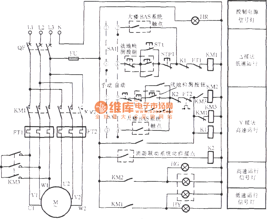
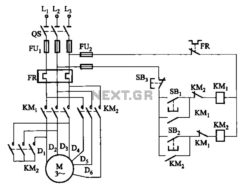
Two speed motor control circuit diagram. The control circuit connects the windings in different configurations causing the speed to change from one rpm to another. Zero crossing detector circuit. Main circuit is a combination of two sub circuits. Thus by varying the delay after which the triac is triggered one can change the speed of motor. Kindly email me the diagrams for star deltor and direct online for a 3speed 1directon 3ph motor have two of them in a bow cutter. For this reason a rearrangement of the circuit elements to form a line diagram is desirable.
Two speed manual motor starter is designed for starting protecting small single phase two. The diagram below illustrates the control circuit needed to accomplish the operation. Wondering how a capacitor can be used to start a single phase motor. First the stop pushbuttons are connected in series to form a nor logic. Please help how to go about this. Zero crossing detector circuit.
Learn how a capacitor start induction run motor is capable of producing twice as much torque of a split phase motor. The line diagram. Next the start pushbuttons are connected in parallel to form an or logic circuit. The speed is controlled through an externally applied varying dc voltage source. Also explain the operation of this motor control circuit. One contactor burnt for high speed and a replced contactor does not engange originally the coils re fed with a nutural and the one i replaced is only working with a phase.
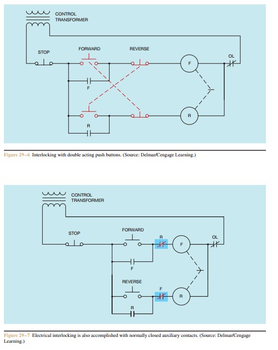
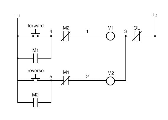
This control circuit is a variation of the three wire control circuit. Also read about the speed torque characteristics of these motors along with its different types. Two speeds two directions tapped wound multispeed 3 phase motor control diagram. Each winding can deliver the motors horsepower at a rated speed. Based on your observations of these two diagrams explain how electromechanical relays are represented differently between ladder and schematic diagrams. Firing angle control circuit.
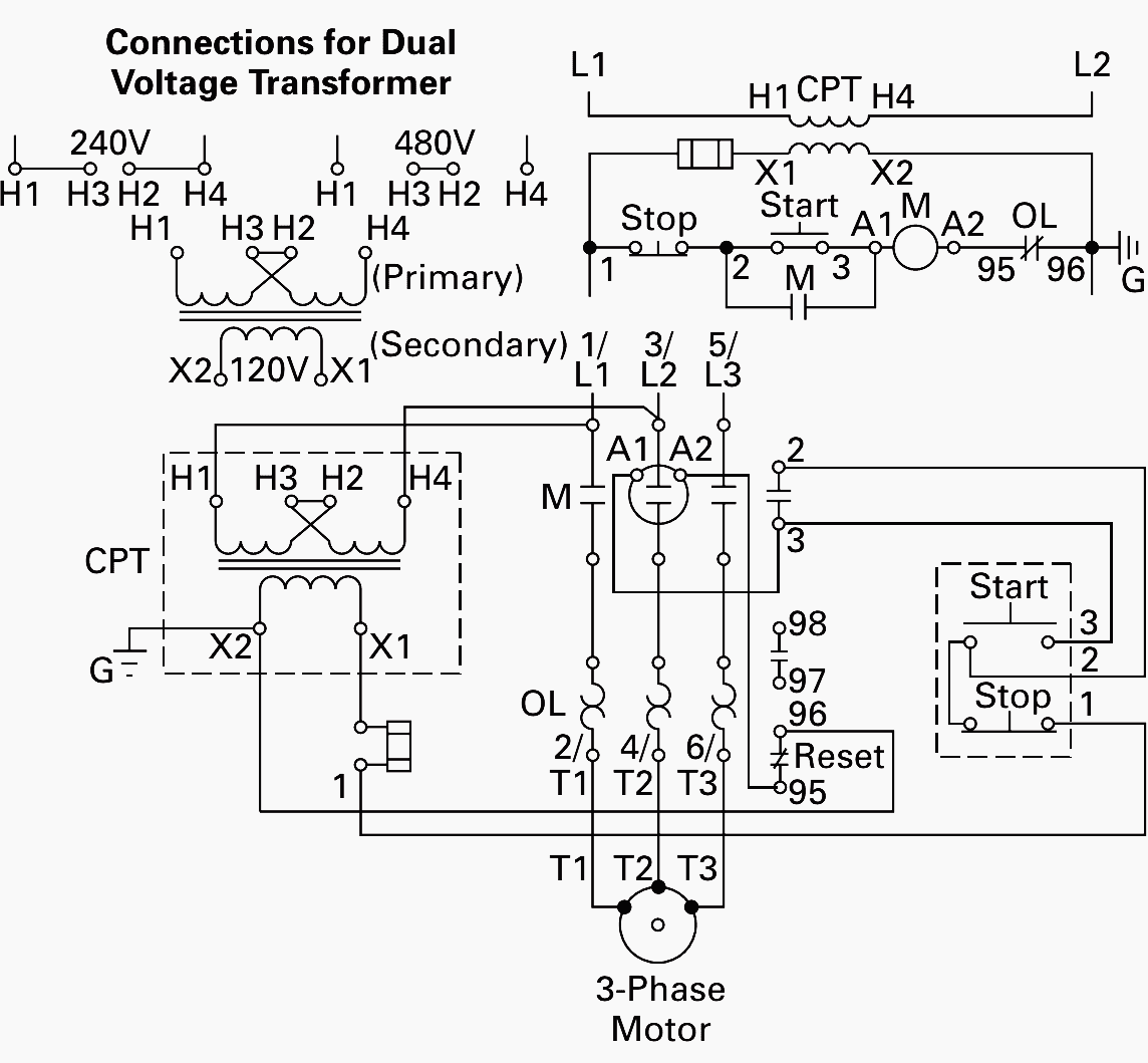
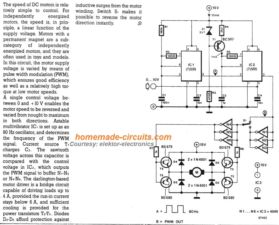
2 speeds 2 directions multispeed 3 phase motor power control diagrams abbreviationsol over load relayno normally opennc normally closelow low speedhigh high seed for forwardrev reverse two speeds two directions multispeed 3 phase motor power diagram power diagram. This will cut the current supplied to motor and so the speed of motor will reduce. Are you fed up with ordinary pwm circuits which do not provide perfect dc motor speed control especially at lower speeds. Interpret this ac motor control circuit diagram explaining the meaning of each symbol. Control circuit until the start button is pressed once again. There are two electrically separate windings housed in the motor.
A typical control circuit for a two speed motor is shown in figure 716. Then check out this outstanding single chip pwm motor speed controller circuit that will give you a complete 360 degrees of continuously varying motor speed control right from zero to maximum. As shown in.

