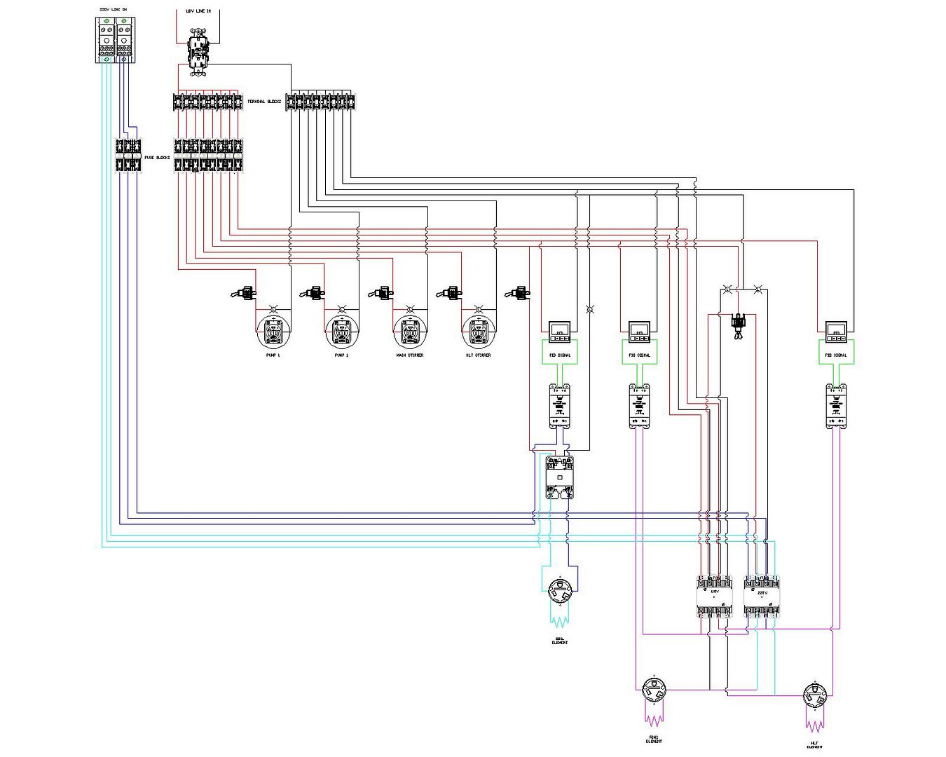
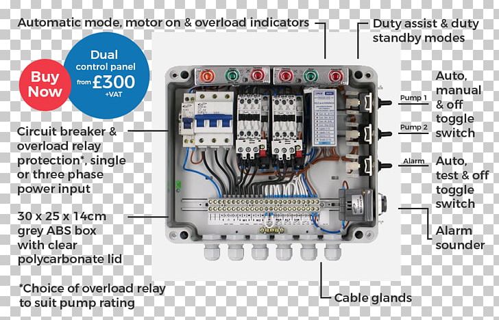
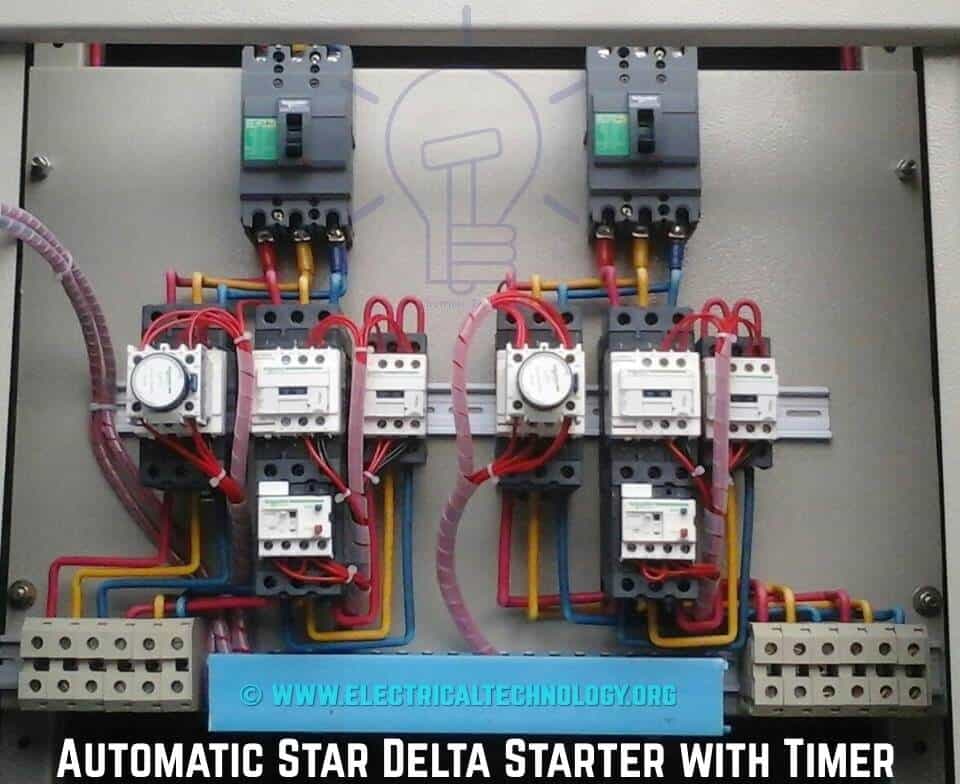
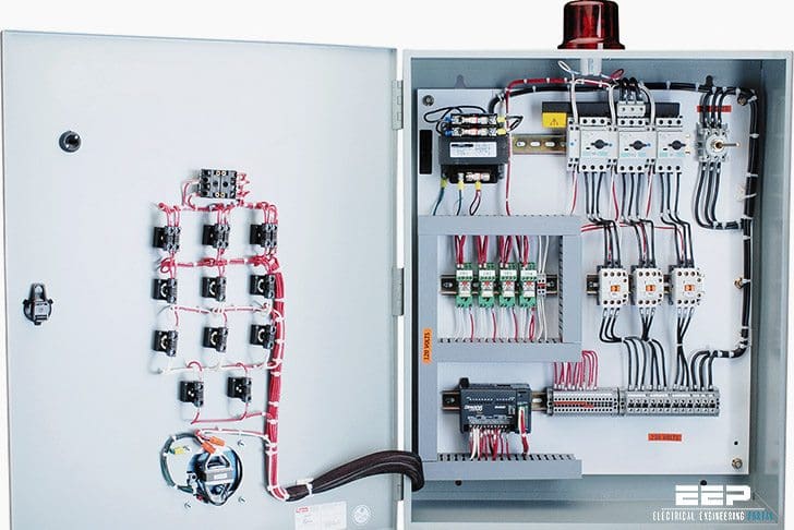
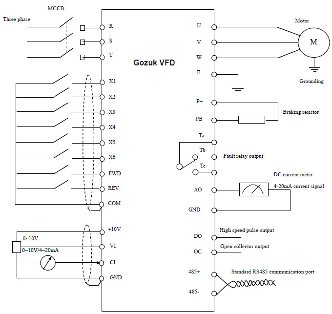
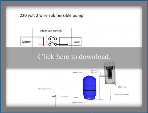
How is a wiring diagram different from a schematic. Now look to see if the breaker takes up two breaker spaces or one.
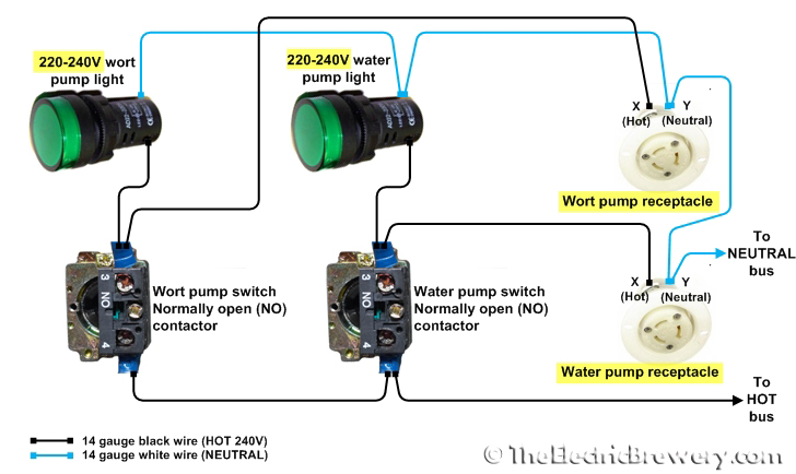
30a Control Panel 240v Only For Int L Use
Pump control panel wiring diagram schematic. It shows the elements of the circuit as streamlined forms and the power and signal connections in between the devices. A schematic shows the plan and also function for an electric circuit but is not worried about the physical design of the wires. The main breaker panel should have a wiring schedule handwritten inside the front door panel. Assortment of pump control panel wiring diagram schematic. Then provide the 240 circuit for the well pump from the panel and at least one 120 volt circuit for lighting and a gfi utility outlet. Wiring diagrams demonstrate how the wires are.
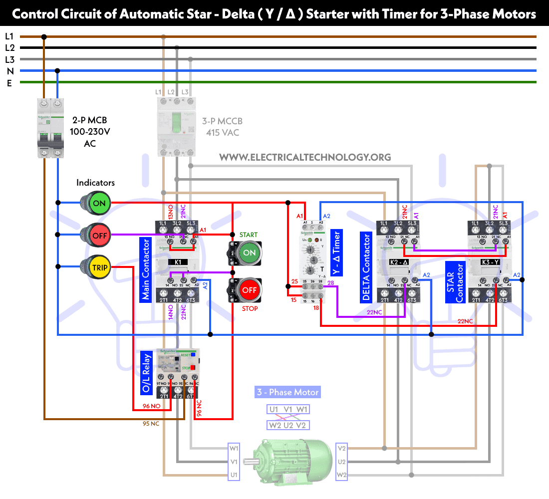
A wiring diagram is a simplified traditional photographic depiction of an electric circuit. Signs that stand for the parts in the circuit and also lines that. Lets start with the most basic float switch. A wiring diagram is a simplified traditional photographic depiction of an electrical circuit. A wiring diagram is a kind of schematic which makes use of abstract photographic signs to show all the interconnections of components in a system. Here is the complete guide step by step.
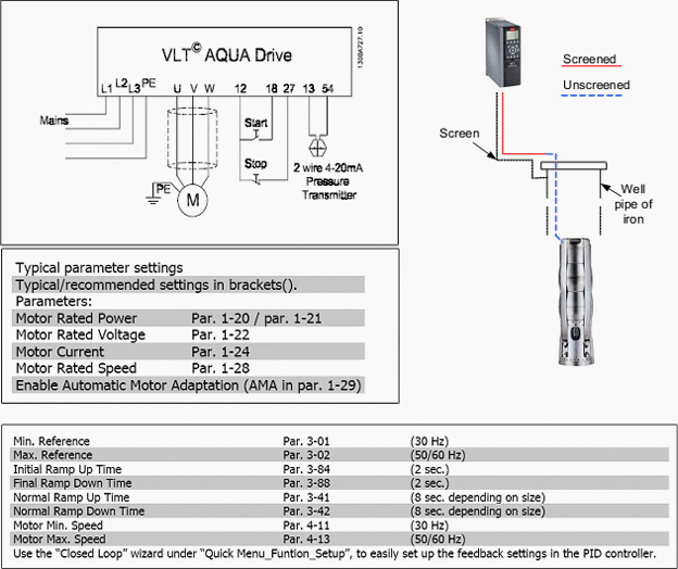
Start at the breaker panel. Electrical wiring diagrams are comprised of 2 things. Collection of submersible pump control box wiring diagram. Single phase submersible pump control box wiring diagram 3 wire submersible pump wiring diagram in submersible pump control box we use a capacitor a resit able thermal overload and dpst switch double pole single throw. Accesstopower motorcontrol in this video we will look at the control wiring for a 3 phase pump panel and how a pump is controlled both in auto mode as well as hand mode. In auto mode the pump.
Duplex pump control panel wiring diagram sample duplex pump control panel wiring diagram lovely nih standard cad. Installing a 240volt 3wire circuit for a well pump panel. A two wire single pole single throw float switchthe rising action of the float can either close ie turn on a normally open circuit or it can open turn off a normally closed circuitinstallation scenarios might include a normally open float switch turning on a pump to empty a tank control schematic 2 or a normally closed. Panel must be ordered with the proper amp rating matching that of the pump. Two spaces is a 220 volt system and one is a 110 volt system. Field wiring diagram panel schematic and installa tion instructions included.
The wiring connection of submersible pump control box is very simple. Pump control panel wiring diagram schematic just whats wiring diagram. Panel can be wired for a single power feed for pump and control circuit or the control circuit can be wired z simplex dry contact for pump running interface to building management. It shows the parts of the circuit as simplified shapes as well as the power as well as signal links between the devices. Use this guide to find which circuit is your submersible pump and turn it off. It may be a better idea to install a larger conduit and pull in a larger 240 volt 3 wire circuit and ground to feed a sub panel.

