By peter june 28 2015. When the cd diagram includes the plc is still pending.
Plc Wiring Diagrams Plc Digital Signals Wiring Techniques
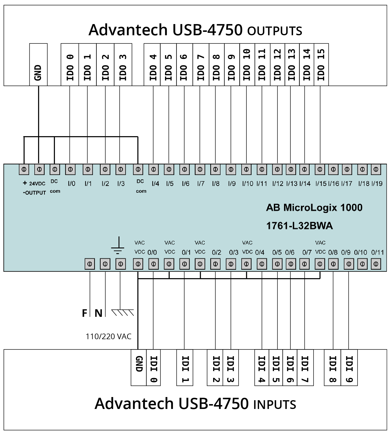
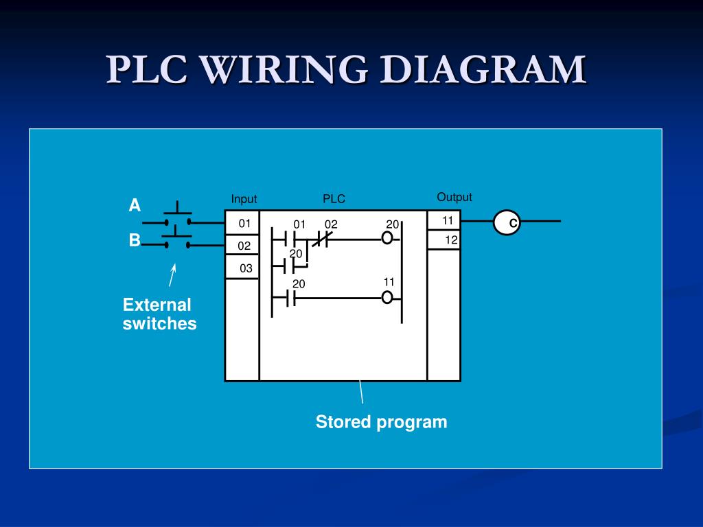
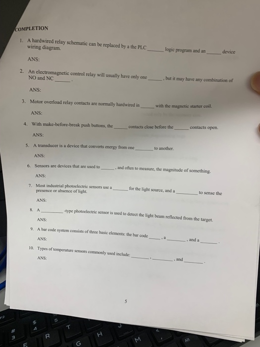
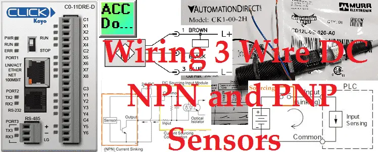
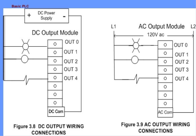
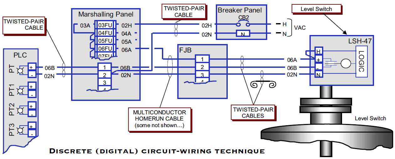
Basic plc wiring diagram. Ladder logic symbols are the basic building blocks for ladder diagrams. Everything inside the dashed box happens inside the plc. In this video you will learn how to convert a basic wiring diagram to a ladder logic plc program. These look like a normally closed nc contact. In order to increase io points on plcs without increasing the number of connections commons are used. The picture to the right shows an example of what the wiring of a plc with 4 inputs would look like.
In this article we are sharing the basic concepts of plc and dcs control systems wiring diagrams for digital input di digital output do analog input ai and analog output ao signals. Right here you will find all the ladder diagram symbols which are described in iec 61131 3. Figure 5 below shows a schematic diagram for a plc based motor control system similar to the previous motor control example. When including a plc in the ladder diagram still remains. Ladder logic symbols all plc ladder diagram symbols. Lets start converting our simple wiring diagram to the plc program in a step by step format.
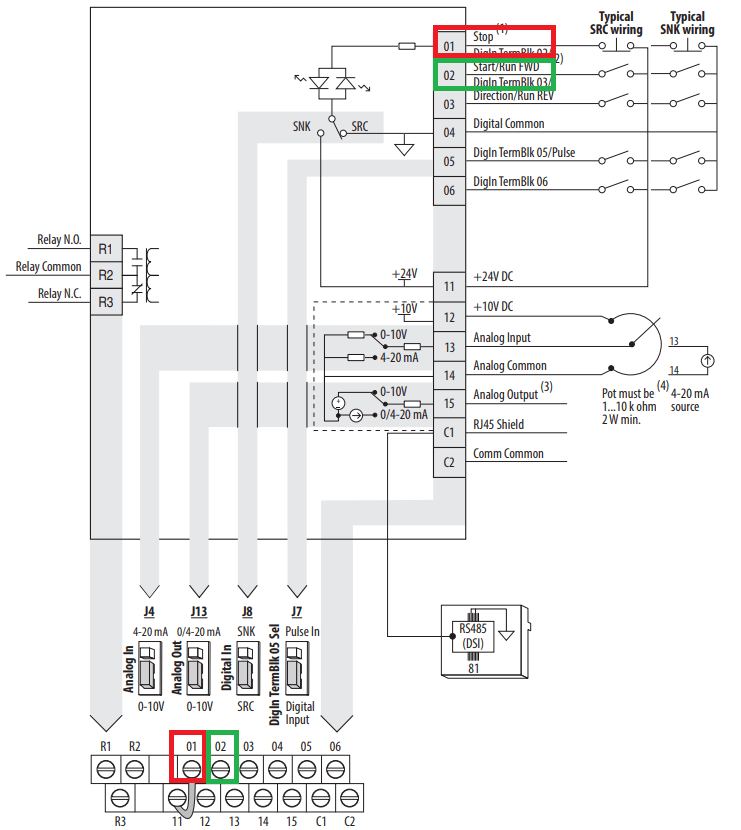
This can be a very handy skill to learn especially if you are converting a machine to plc control. Just like on the diagram we start with the stop push button. Drawing wiring and power control circuit diagrams on pc the 10 basic rules learn the 10 things you need to know in order to draw electrical wiring diagrams plc diagrams and power control circuit diagrams quickly and effectively using an advanced electrical design software as pcschematic automation. Im using the siemens tia portal as the plc programming software. Note that these diagrams are without a barrier or isolator fuses and surge protector for keeping it very simple and understandable. Shows which direction power flows through the circuit.
Figure 1 shows the wiring diagram for a three phase motor and its corresponding three wire control circuit where the auxiliary contacts of the starter seal the start push button. But it does tend to become more complex. This figure shows the e stop wired to cutoff power to all of the devices in the circuit including the plc. E stop wired cut to power in all devices of the circuit including. But it gets more complicated. These are the circled items in figure 2.
It will be represented with an examine off bit. To convert this circuit into a plc program first determine which control devices will be part of the plc io system. This figure shows that the plc. The symbols are available for download in all formats and in a pdf file. In this lesson well define the make break and output enable instructions common to most plcs as well as differentiate between electrical continuity as required by traditional hardwired relay. Figure 5 below shows a schematic diagram for a plc based motor control system similar to the previous motor control example.
Gallery of Basic Plc Wiring Diagram