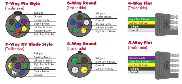
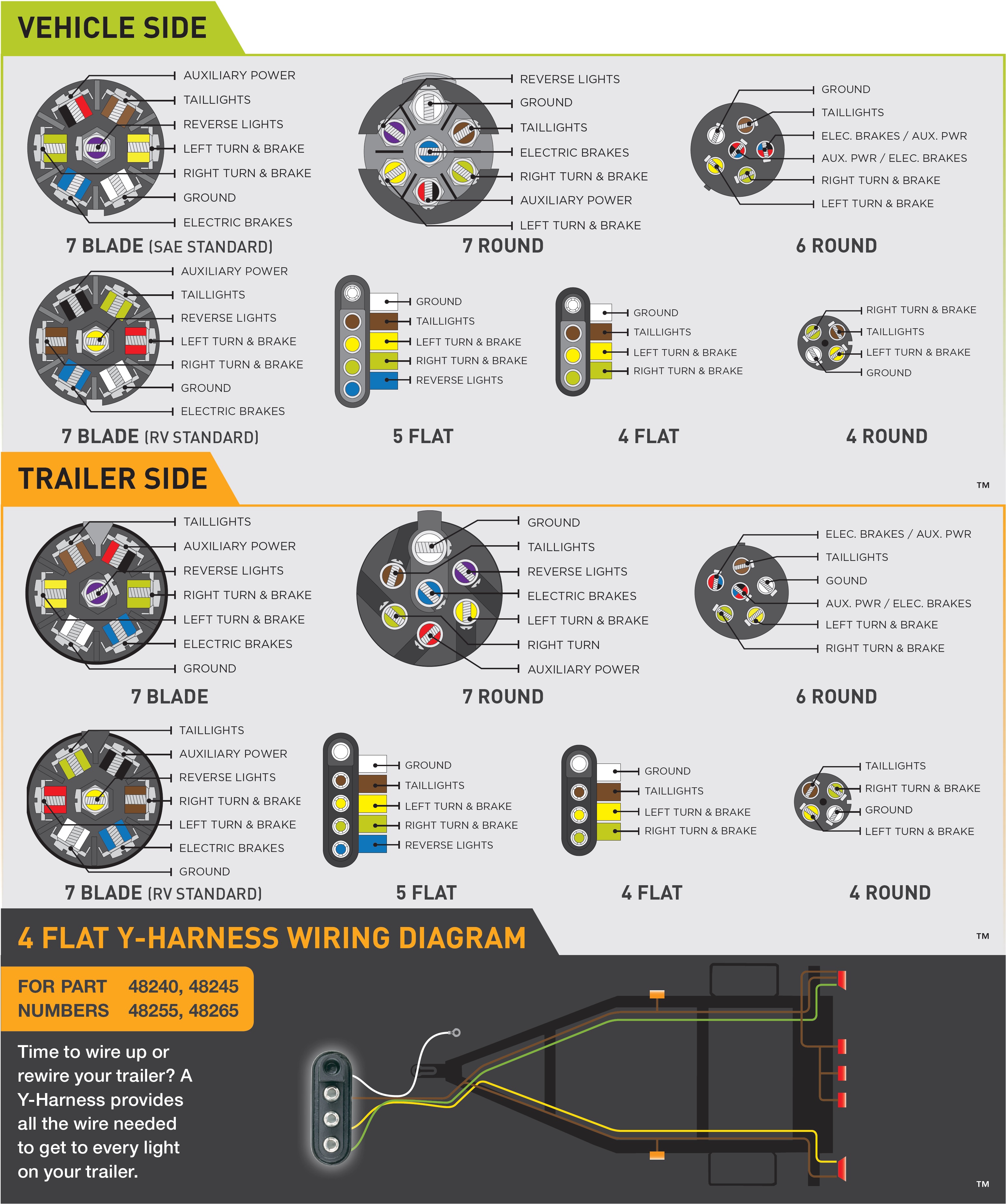
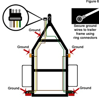
A wiring diagram is a straightforward aesthetic depiction of the physical links as well as physical layout of an electric system or circuit. 4 way trailer connectors are typically used on small trailers such as boat snowmobile utility and other trailers that that do not use brakes.

Trailer Wiring Guide
Boat trailer plug wiring diagram. Large 5th wheel trailers. They also provide a wire for a ground connection. We recommend these standards because they are pretty universal. Wiring diagram for boat trailer plug 2019 wiring diagram for 4 pin exactly what is a wiring diagram. 7 way trailer connectors are used by the following vehicle types. Use on a small motorcycle trailer snowmobile trailer or utility trailer.
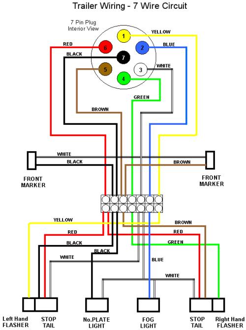
7 way trailer wiring diagram is explained in details in the picture and the table below. The following trailer wiring diagrams and explanations are a cross between an electrical schematic and wiring on a trailer. 7 pin trailer wiring diagram with brakes. 34 inch by 1 inch 6 way rectangle connectors right turn signal green left turn signal yellow taillight brown ground white. 6 way system rectangle plug. It shows how the electrical wires are adjoined and also can also reveal where fixtures and parts could.
The red and blue wire can be used for brake control or auxiliary. Boat trailer wiring diagram 4 pin trailer light wiring trailer wiring harness 4 pin trailer wiring trailer plug 4 pin trailer connector boat web site http. On most recreational vehicles. 4 way trailer connectors are. That said for specific situations there are industrial standards with different connectors and wire arrangements. As the name implies they use four wires to carry out the vital lighting functions.
The four wires control the turn signals brake lights and taillights or running lights.


