Contactor wiring with start stop push button. Wiring diagram single motor with start stop switch.

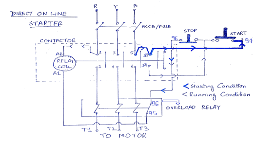
What Is Dol Starter Direct Online Starter Wiring And Working
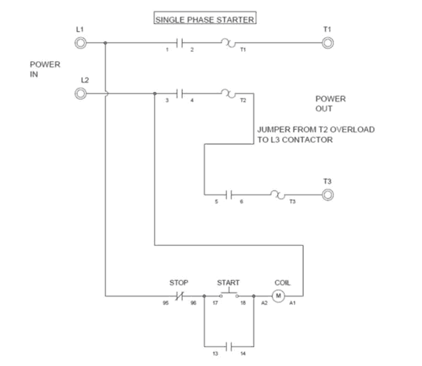
Start stop push button wiring diagram single phase. L2 i c start i i1 i 1 i i lr 0 i. Push to make ptm switch use to start the motor and push to brake ptb switch use to stop the motor. The most common use of 3 wire control is a startstop control. The stop button is normally closed and is wired in series with the control power so that when it is pressed control power is removed from the coil and the contactor opens. Wiring diagrams sometimes called main or construc tion diagrams show the actual connection points for the wires to the components and terminals of the controller. The below wiring diagram shows how we would assemble a complete motor starter with a startstop button for a single phase motor utilizing a 3 pole contactor.
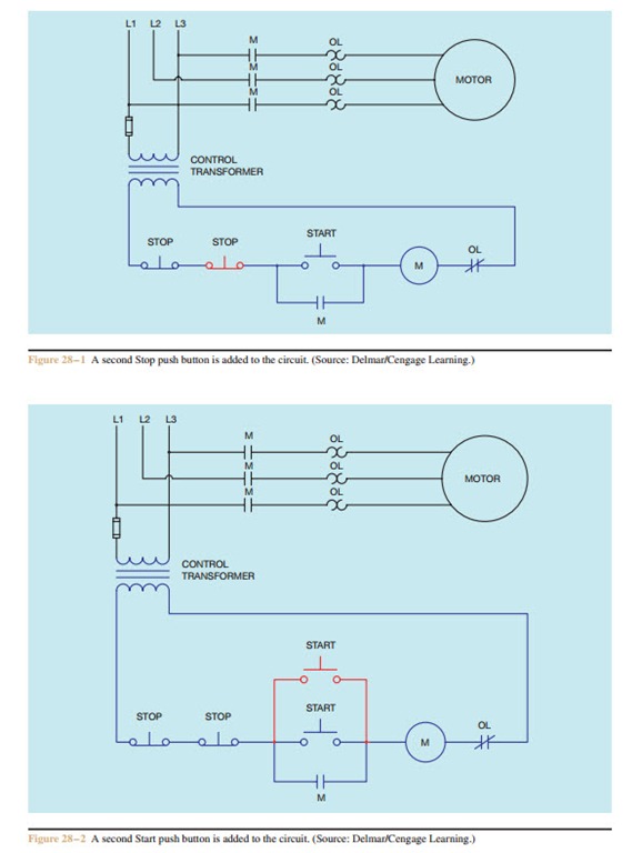
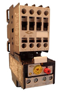
The start and stop circuits could alternatively be controlled using a plc. This diagram is for single phase motor control. It uses a contactor an overload relay one auxiliary contact block a normally open start pushbutton a normally closed stop pushbutton and a power supply with a fuse. Typical wiring diagrams for push button control stations start stop control wiring diagrams 4 single station maintained contact push buttons t t l1 undervoltage release ol. They show the relative location of the components. For motors over 1 hp an overload detector is used which has a normally closed contact that is put in series with the stop button.
Wiring diagram single motor with start stop switch. When you press the start button and the stop button is not pressed the 24vdc relay energizes and it pulls in the r1 contactor that feeds three phase power to the motor. 77 i i i i i i. Start stop wiring basics duration. In the above one phase motor wiring i first connect a 2 pole circuit breaker and after that i connect the supply to motor starter and then i do cont actor coil wiring with normally close push button switch and normally open push button switch and in last i do connection between capacitor. They can be used as a guide when wiring the controller.
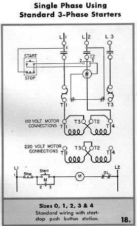
Figure 1 is a typical wiring diagram for a three phase mag. The above diagram is a complete method of single phase motor wiring with circuit breaker and contactor. L m e 1 the start button mechanically maintains the contacts that take the place of hold in contacts. To get start or stop the motor use a push button switch as a trigger a motor. Electric parts needed for the wiring above. Properly connect a single phase motors to a three phase starter.
Single phase submersible starter connection with diagram in hindi 2020 duration. We hope this helps further your understanding of motor controls. Single phase dol starter wiring diagram animation. B1 mcb. Start stop wiring basics duration. See image below for an example of 3 wire control being used to pull in a contactor to start a 3 phase motor.
Gallery of Start Stop Push Button Wiring Diagram Single Phase