With these diagrams below it will take the guess work out of wiring. The carter system was a method of wiring 3 way switches in the era of early knob and tube wiringthis now obsolete wiring method has been prohibited by the usa national electrical code since 1923 even in new knob and tube installations which are still permitted under certain circumstances.

Alternate 3 Way Switches Electrical 101
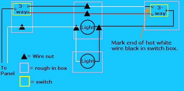
California three way switch diagram. This might seem intimidating but it does not have to be. How to wire 3 way switch. This wiring system may still be encountered in older grandfathered electrical installations. Take a closer look at a 3 way switch wiring diagram. The white wire between switches is not being used as a neutral. Conventional 3 way wiring is not very complexwith conventional wiring the line line voltage connects to the common of one switch.
Pick the diagram that is most like the scenario you are in and see if you can wire your switch. 3 way switch wiring diagram with line and load in the same switch box. An example of three way switch wiring with the line and load in the same 4 square electrical box. The alternate 3 way switch wiring configuration california or west coast was used as a way to wire 3 way switches and be able to supply line voltage to either switchthis configuration is no longer allowed as the neutral is not present in each switch box. This method is commonly used by professional electricians. 3 way switch wiring diagram.
A dead end 3 way switch wiring method. Conventional and california diagram. There are 2 variations of dead end 3ways. In the above diagram the white wire must be re identified as a hot wire at each switch location. Extending the switch leg over to the common as shown in the photo above or extending the hot over to the common as described below.


/Three-WaySwitch-56a27f675f9b58b7d0cb52c8.jpg)


