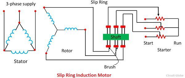
The slip ring induction motor has two distinctly separate parts one is the stator and other is the rotor. The aim behind the development of the project is to limit the current at starting of motor and to develop the high starting torque.

Slip Ring Induction Motor Youtube
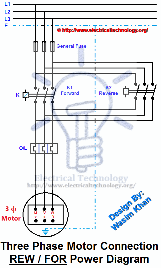
Slip ring motor starter diagram pdf. Slip ring induction motor application slip ring induction motor provides high starting torque. Three phase induction motor provided with the different starter like star delta starter autotransformer starter and dol starter etc. However we selected the rotor. A slip ring is an electromechanical device that allows the transmission of power and electrical signals from a stationary to a rotating structure. It can improve mechanical performance simplify system operation and eliminate damage prone wires dangling from movable joints. Three phase motor control installation wiring diagrams.
A slip ring motor also requires a larger space for the motor and its. It consists laminated cylindrical core which has a semi closed slot at the outer periphery and carries three phase insulated winding. A slip ring motor is expensive as are its controls compared to a squirrel cage motor. There are different methods of starting of 3 phase slip ring induction motor. Why using a starter for slip ring motors. A squirrel cage motor is thus preferred to a slip ring motor.
If the motor is started directly. The frame voltage is the open circuit voltage when the rotor is not rotating and gives the measure of turns. So this motor is used in applications like lifts pumps mills where we require high starting torquegenerally induction motor provides low starting torque as compared to dc series motors but this disadvantages of the induction motor can be overcome by slip ring induction motor. As discussed earlier a slip ring induction motor is an asynchronous motor as the rotor never runs in synchronous speed with the stator poles. The motor which employing the wound rotor is known as a slip ring induction motor or phase wound motor. A slip ring can be used in any electromechanical system that requires rotation while transmitting power or signals.
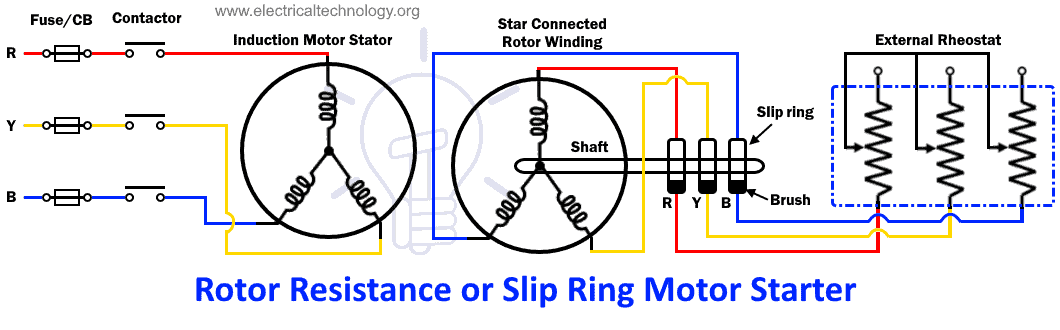
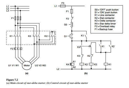
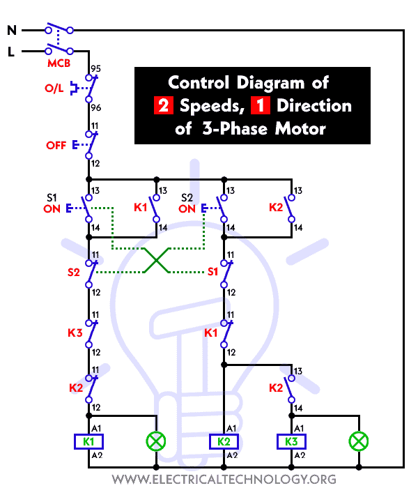
Three phase slip ring rotor starter control diagram control diagram. Check more diagrams here. Learn more about the construction and operation of a slip ring induction motor. Definition of slip ring motor. In order to start a slip ring motor the accelerating torque has to be sufficiently higher than the resisting torque. Higher is the inertia higher has to be the accelerating torque otherwise the start will be very long and the motor can be damaged by the heating.
For slip ring induction motor by providing external resistance in rotor circuit we can also limit starting current. The construction of a stator is the same for both the squirrel cage and slip ring induction motor. The stator circuit is rated as same in the squirrel cage motor but the rotor is rated in frame voltage or short circuit current. It also requires meticulous and periodic maintenance of the brushes brush gear slip rings external rotor resistances etc.
Gallery of Slip Ring Motor Starter Diagram Pdf