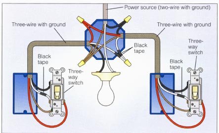
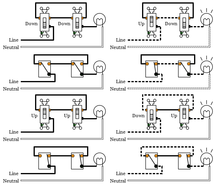
Take a closer look at a 3 way switch wiring diagram. With a pair of 3 way switches either can make or break the connection that completes the circuit to the light.

Replacing 3way Switch With Motion Sensor Doityourself Com
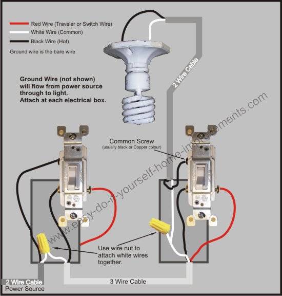
Cooper 3 way light switch wiring diagram. Pick the diagram that is most like the scenario you are in and see if you can wire your switch. Three wire cable runs between the switches and 2 wire cable runs to the light. This switch is designed to replace 15 amp 3 way switches and provide light control from 2 locations. For 3 way applications wire the sensor switch according to wiring diagram 2a or 2b using the wire nuts provided. Returned prepaid to cooper wiring devices quality control department at cooper circle peachtree city switch cooper wiring devices installation. Wiring a 3 way light switch is certainly more complicated than that of the more common single pole switch but you can figure it out if you follow our 3 way switch wiring diagram.
The leviton 15 amp 3 way light switch features the leviton 15 amp 3 way light switch features a clear design that illuminates when turned off to help you locate the switch in dark rooms. Wiring devices connectivity eatons full line of decorator and standard toggle switches are perfect for residential and commercial applications. Remove the existing switch in the location where the sensor will be installed. This might seem intimidating but it does not have to be. Interested in a 4 way switch wiring diagram. Wiring diagram 3 way switch with light at the end.
See alternate 3 way switch wiring configuration for another way 3 way switches may be wired. The ground wire is pigtailed with a wire connector at the switch boxes and the ceiling box. The sensor black wire will connect to either one of the black wires in the wall box. The diagrams below show the conventional wiring for 3 way switches. Unfortunately not all 3 way switches are wired the conventional way. So you turn in for bed and start some nighttime reading and then find yourself nodding off between pages.
With these diagrams below it will take the guess work out of wiring. The sensor may be placed at either end of the 3 way circuit. The black and red wires between sw1 and sw2 are connected to the traveler terminals. Power through switch light is controlled by two three way switches with the light between the switches and the power first going through a switch then to the light and onto the second three way switch. If you have any problems with these switches it may be best to call an electrician. Cooper lighting home security system motion sensor user manual.
In this diagram the electrical source is at the first switch and the light is located at the end of the circuit. Our heavy duty and hazardous area switches provide safety reliability and long term durability in industrial environments. Cooper wiring diagram single pole light switch explained bination double leviton three way dimmer switch wiring diagram fresh cooper 3 for with wiring diagram cooper 3 way switch refrence. Fixture between two three way switches. Wiring a 3 way light switch.


