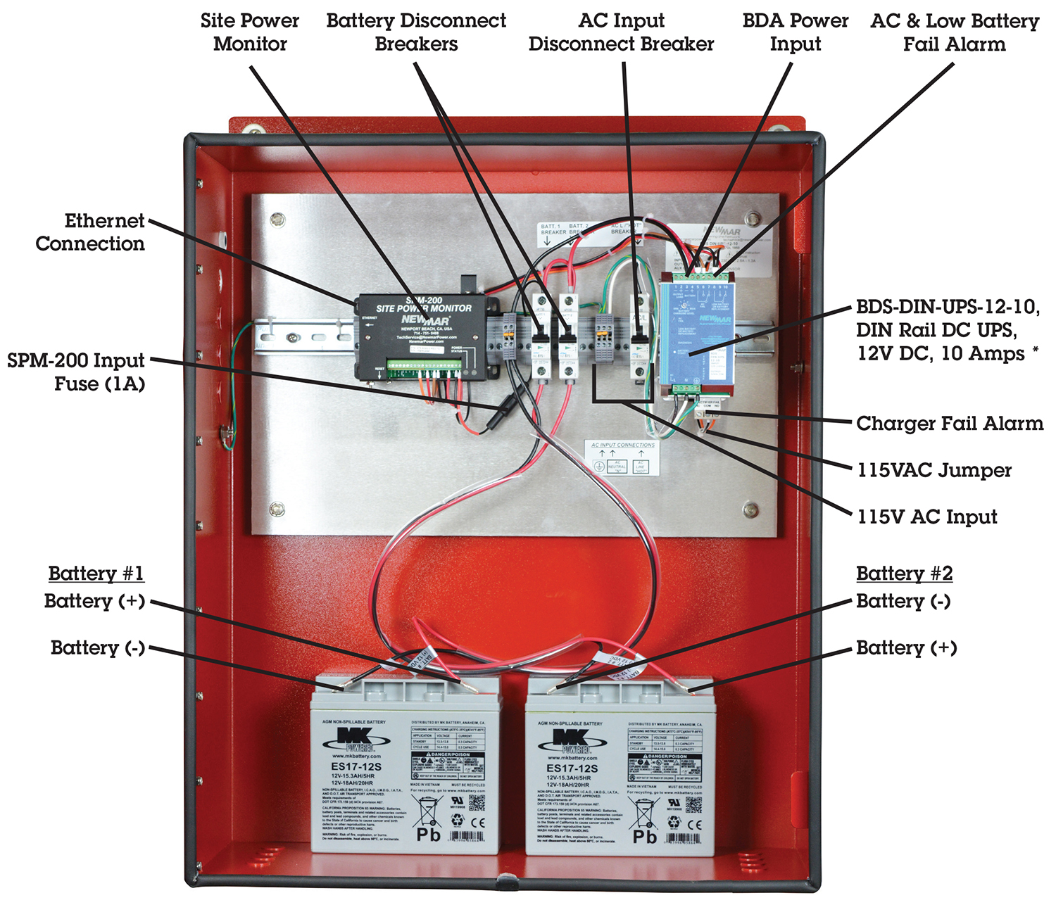
View a toyota pickup wiring diagram today to keep your 1989 1996 toyota pickup land cruiser or 4runner repaired. First we start from ups battery connection.

Fz 3805 Maintenance Byp Switch Wiring Diagram Wiring Diagram
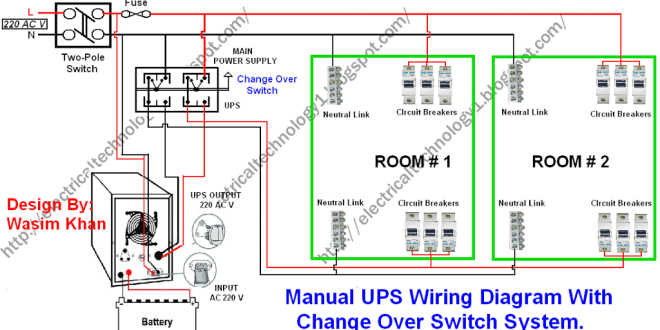
Ups electrical wiring diagram. These detailed diagrams help you find the source of any electrical issue in your toyota. To review a wiring diagram first you have to know exactly what basic components are included in a wiring diagram and also which pictorial symbols are used to represent them. Once you find the damaged 4runner ignition coils sensors or wiring connectors restoring your vehicle is an easy diy task. In the diagram a 12 volt upsinverter shown with battery connection. The usual elements in a wiring diagram are ground power supply wire and link output gadgets buttons resistors reasoning entrance lights etc. Now according to the below ups connection diagram connect an extra wire phase to those appliances where we have already connected phase and neutral wires from power house db ie two wire as phase live as shown in the below fig.
How to connect a portable generator to the home supply 4 methods below is a given ups inverter connection and wiring diagram to the home supply. From this ups you can get two power supply of different voltage one is 12v unregulated dc power supply and another is 5v regulated dc power supply. In the below ups wiring diagram. The circuit shows that only two rooms of the home are depends on the ups and batteries as well as main supply to maintain the uninterruptible power to the connected appliances and load such as lighting points and fans etc and the. Also a two 12 volts 150 watts solar panel shown which is connected in parallel connection. You can easily make a upsuninterruptible power supply at your home.
Related electrical wiring tutorial. Ups wiring diagram with solar panel charge controller battery connection and wiring installation for house. The ups can deliver up to 2a current. To read a wiring diagram initially you have to recognize exactly what essential elements are included in a wiring diagram and also which photographic symbols are used to represent them. It is a very simple ups circuit diagram. Provide continuous supply in case of supply outage protection against voltage spikes frequency fluctuation and against distortion in voltage wave form.
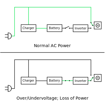
Ups uninterruptible power supply is a device used for protection against over voltage under voltage. Ups inverter wiring diagram with auto manual changeover switch system. Here a circuit diagram of ups is given. The circuit drawn pertains to a regular industrial ups uninterruptible power supply which shows how the batteries take control during an outage in electrical supply or variation beyond the normal limits of the voltage line without disruption on the operation providing a steady regulated output 5 volts by lm7805 and an unregulated supply 12 volts. A wiring diagram is a simplified conventional photographic representation of an electrical circuit. The typical elements in a wiring diagram are ground power supply cord and link outcome devices buttons resistors logic entrance lights etc.
Collection of ups maintenance bypass switch wiring diagram.


