This opens the switch and breaks the electrical connection. A centrifugal switch is an electrical switch that operates using the centrifugal force created from a rotating shaft most commonly that of an electric motorthe switch is designed to activate or de activate as a function of the rotational speed of the shaft.

Mw 8043 Centrifugal Switch Wiring Diagram 11 Wiring Diagram
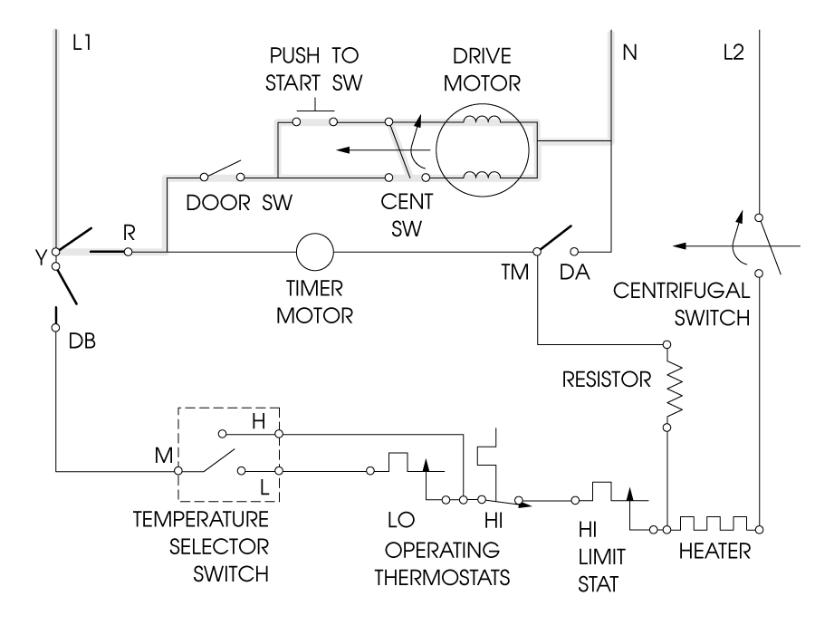
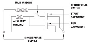
Centrifugal switch diagram. This motor is called. Perhaps the most common use of centrifugal switche is within single phase splitphase induction motors. Centrifugal switches for electrical applications are essential for the proper functioning of electrical motors. Reassemble all components in reverse order of removal. When the motor stops a spring pulls the switch mechanism closed again. I have not seen any listed anywhere.
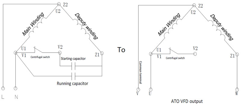
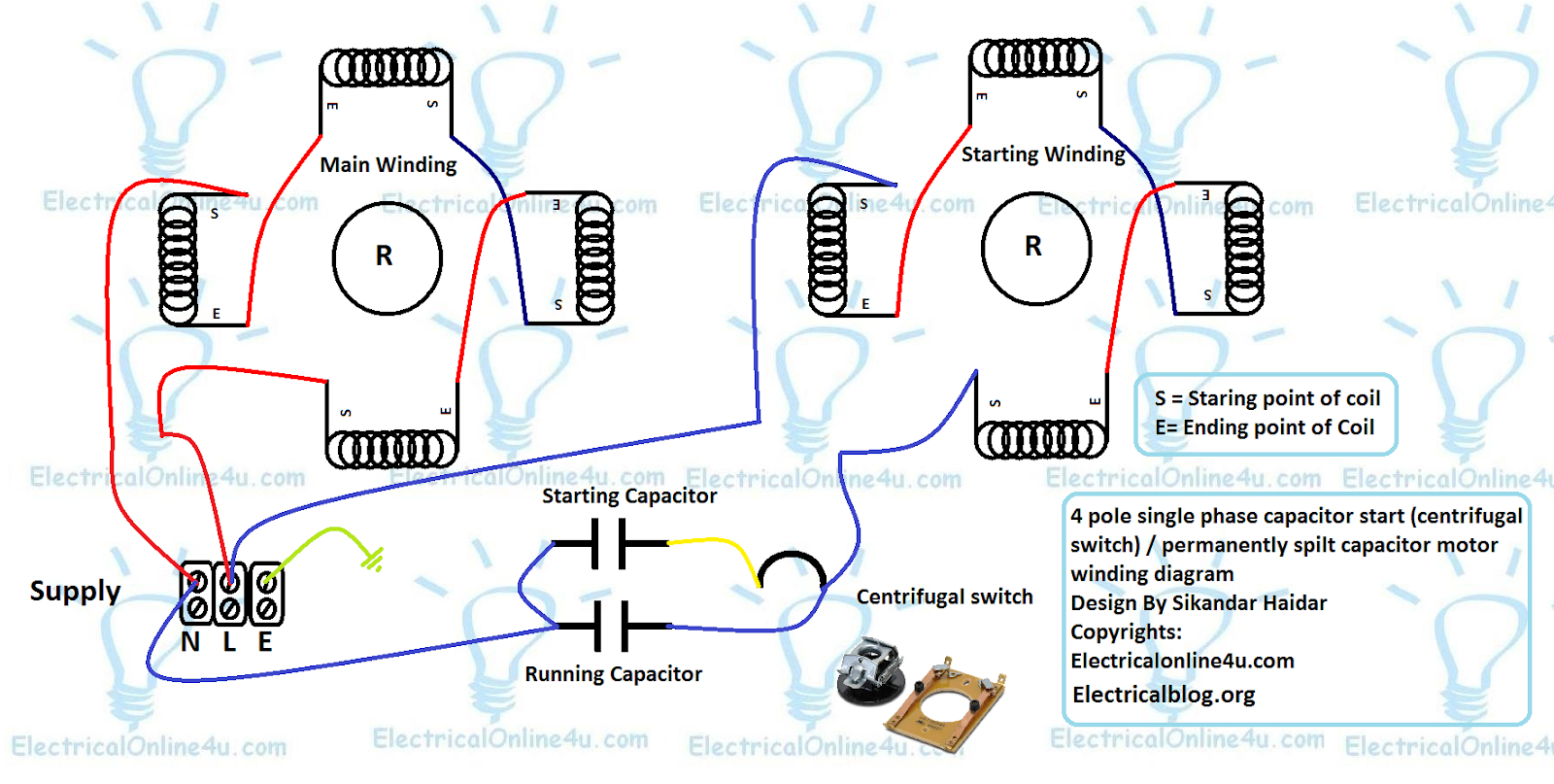
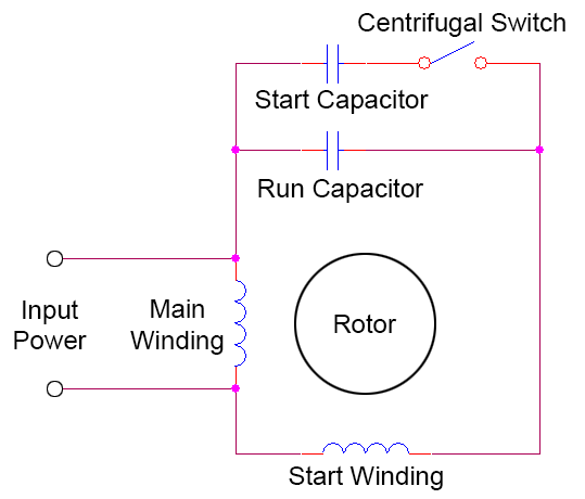
Capacitor start motor because it uses a capacitor to start itself. An electronic switch does not respond to the speed of the motor shaft like a centrifugal switch does but has a timed disconnect. Centrifugal switch replacement and adjustment 5 11. 4 pole induction motor winding diagram with centrifugal switch and capacitors. As the motor reaches a certain speed a mechanism in the switch responds to centrifugal force pulling against it. A centrifugal switch is used for starting capacitor.
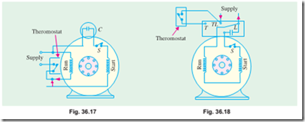
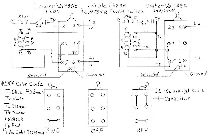
It is important to point out from the phasor diagram that the phase difference between im and is is almost 80 degrees as against 30 degrees in a split phase induction motor. It allows the starting windings to be engaged for 74 seconds and then breaks the circuit. It is also possible to buy an electronic switch to replace the centrifugal switch. Motorsnidec and weg electric. The both winding connection shown with power supply acv. The switch is designed to activate or de activate as a function of the rotational speed of the shaft.
A 1920s patent for. Install the new switch and wires at the same locations. Vacuum out the motor so all built up dust and contaminants are removed. Install the actuator and adjust the switch as described in step 6. The main winding connection shown and also the starting winding connection shown. In the below 4 pole motor winding diagram.
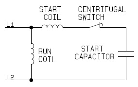
Smith baldor bluffton motor works leeson electric marathon electric regal beloit corporation torq us. The centrifugal switch is normally closed and conducts electricity. When the motor reaches about 75 of the full load speed the centrifugal switch s opens and thus disconnecting the starter winding and the capacitor from the main winding. Centrifugal switch is connected with starting capacitor and this. Eis supplies centrifugal switches from top suppliers ao. A centrifugal switch is an electric switch that operates using the centrifugal force created from a rotating shaft most commonly that of an electric motor or gasoline engine.
Make sure that all wires are routed away.
Gallery of Centrifugal Switch Diagram