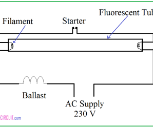
Also internal parts of a tube light shown. This causes electrons in the gas to emit.

Tube Light Wiring Connection Diagram In 2020 Tube Light
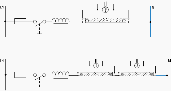
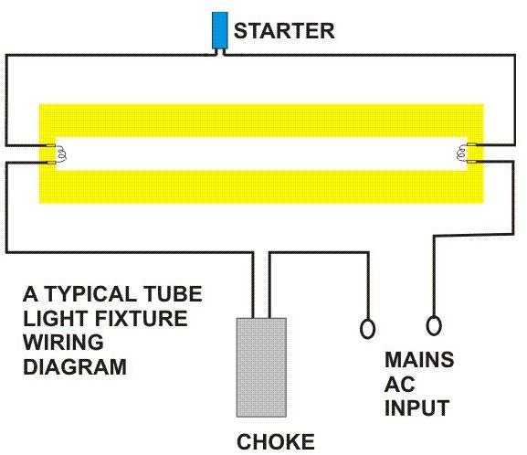
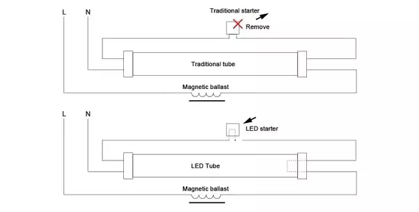
Choke connection in tube light. Here you will learn how to connect tube light with choke starter at home. Fluorescent tube light internal circuit diagram. Tube light connection diagram shown here is suitable for common type fluorescent tubelight. Here the proper circuit diagram of tube light given. The total electrical components for single tube light installation are. A tube light is not connected in the supply main directly.
A choke is connected in one end of the tube light and a starter is in series with the circuit. Fluorescent lamps or tubelight work by ionizing mercury vapor in a glass tube. The purpose of the choke is to provide a very high voltage initially between the filaments across the two ends of the tube light. The connection of tube light is very simple. How to check tube light choke starter capacitor cfl bulb soldering iron by using series test duration. Rajput technical 1214785 views.
Again once the gas in the tube is ionized the choke provides a low voltage. Due to the sudden change of supply the chock will generate around 1000volts. When supply is provided the starter will interrupt the supply cycle of ac. Although it operates at 230 v 50 hz some auxiliary electrical components are used to insert in this installation to support the tube light operational principle. It is electromagnetic ballast or electronic. Tube light connection with electronic choke how does tube light work.
Tube light circuit diagram.


