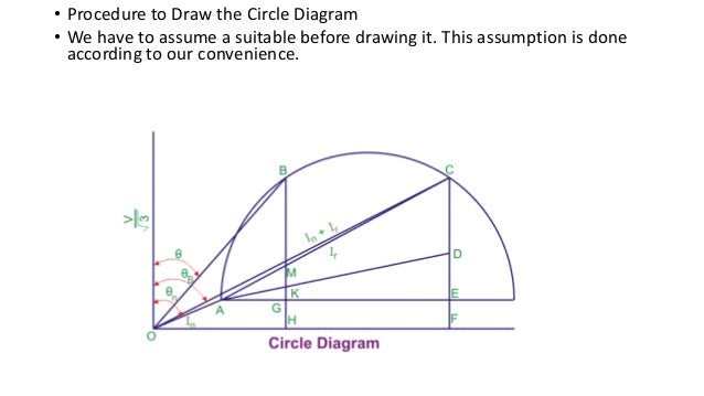
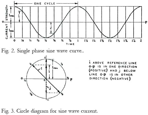
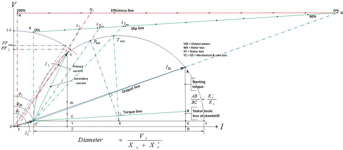
The locus diagram of such a current phasor is circular in nature and hence called circle diagram of a three phase induction motor. And its based on the approximate equivalent circuit.
Induction Motor Asynchronous Motor Ppt Download
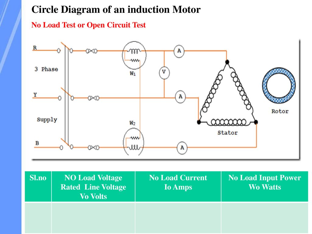
Circle diagram of induction motor. Circle diagram of induction motor duration. The complete circle diagram of induction motor can be drawn with the help of data found from a no load test b blocked rotor test c stator resistance test d all of the above. The motor circle diagram also known as a heyland behrend or ossanna diagram is simply a graphical representation of the locus of induction motor stator current from zero speed to synchronous speed. Kaluva brahmanandam 106921 views. The circle diagram of an induction motor is very useful to study its performance under all operating conditions. It is commonly used to illustrate the performance of transformers alternators synchronous motors and induction motors.
The concept of the circle diagram was conceived in the late 19thcentury but is today no longer commonly utilized by engineers. To understand the circle diagram of induction motor we should first know what is the circle diagram. Blocked rotor test on induction motor is used to find out a leakage reactance b power factor on short circuit. The construction of the circle diagram is based on the approximate equivalent circuit shown below. Using this diagram all the performance characteristics of an induction motor like power factor efficiency stator losses rotor losses maximum output maximum torque etc. It is the diagrammatic representation of the performance of the induction motor.
A circle diagram is a graphical representation of the performance of an electrical machine. Cogging crawling effect in a 3 phase induction motor interview question. The circle diagram can be drawn for alternators synchronous motors transformers induction motors. The circle diagram for an induction motor cannot be used to determine a efficiency b power factor c frequency d output. The circle diagram is a graphic representation of the performance of the machine and its drawn in terms of the locus of the input voltage and current. It is very useful to study the performance of an electric machine under a large variety of operating conditions.
The heyland diagram is an approximate representation of circle diagram applied to induction motors which assumes that stator input voltage rotor resistance and rotor reactance are constant and stator resistance and core loss are zero.
Gallery of Circle Diagram Of Induction Motor