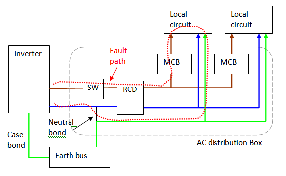
A n ol ol ol v. Demand of these three circuits must not exceed rating of rcd ol n n n a neutral link do not earth ol clipsal rcd 2 4n 1 3n a mains switch a e n n an.

Lk 1349 Rcd Mcb Wiring Diagram Images Of Rcd Mcb Wiring
Clipsal rcd wiring diagram. How to wire rcd residual current device. View the rcd44030 product features specifications documents and related faqs. Please refer the attached document connection in 3p rccb. Max 4 residual current devices non delayed 415v 40a 30ma 4 pole 4 module. The clipsal resi max range. Understanding your consumer unit layout identifying conductors spds mcbs and rcds fuse box duration.
You can follow the same document for connection in three phase without neutral. For balanced 2 and 3 circuits no neutral is required a a e n mains switch main neutral link clipsal rcd 3 n 1 5 2 n 4 6 a to rcd protected circuits n a n to hws. View the 4rc44030 product features specifications documents and related faqs. In my last published post i shared a diagram about double pole rcd wiring and now in this post we also publish a diagram about rcd breaker but this diagram is about 4 pole rcd which we can use in 3 phase 4 wire system for protection. If you are using acti9 range rccb you dont need to add the resistor with iid acti9 rccb. Gsh electrical 72071 views.
Clipsal rcbm 4rcbm and 4rcbe series combined mcbrcd wiring diagram nn a ol n main neutral link a n to unprotected circuits n a v v v v to rcd protected circuit note. It shows how the electrical wires are interconnected and can also show where fixtures and components may be connected to the system. Clipsal rc and 4rc series residual current device wiring diagrams 1 2 main switch single phase e 3n 4n clipsal rcbm 4rcbm and 4rcbe series combined mcbrcd wiring diagram a warning combined max. A wiring diagram is a simple visual representation of the physical connections and physical layout of an electrical system or circuit. Series 4 resi max residual current devices 4 pole 4 modules 415v 40a 30ma. All clipsal resi max products fit easily into clipsal switchboards enclosures and meter boxes.
In this single phase home supply wiring diagram the main supply single phase live red wire and neutral black wire comes from the secondary of the transformer 3 phase 4 wire star system to the single phase energy meter note that single phase supply is 230v ac and 120v ac in usthese two lines line and neutral from energy meter are. Busbars and other accessories are also available for your installation.


