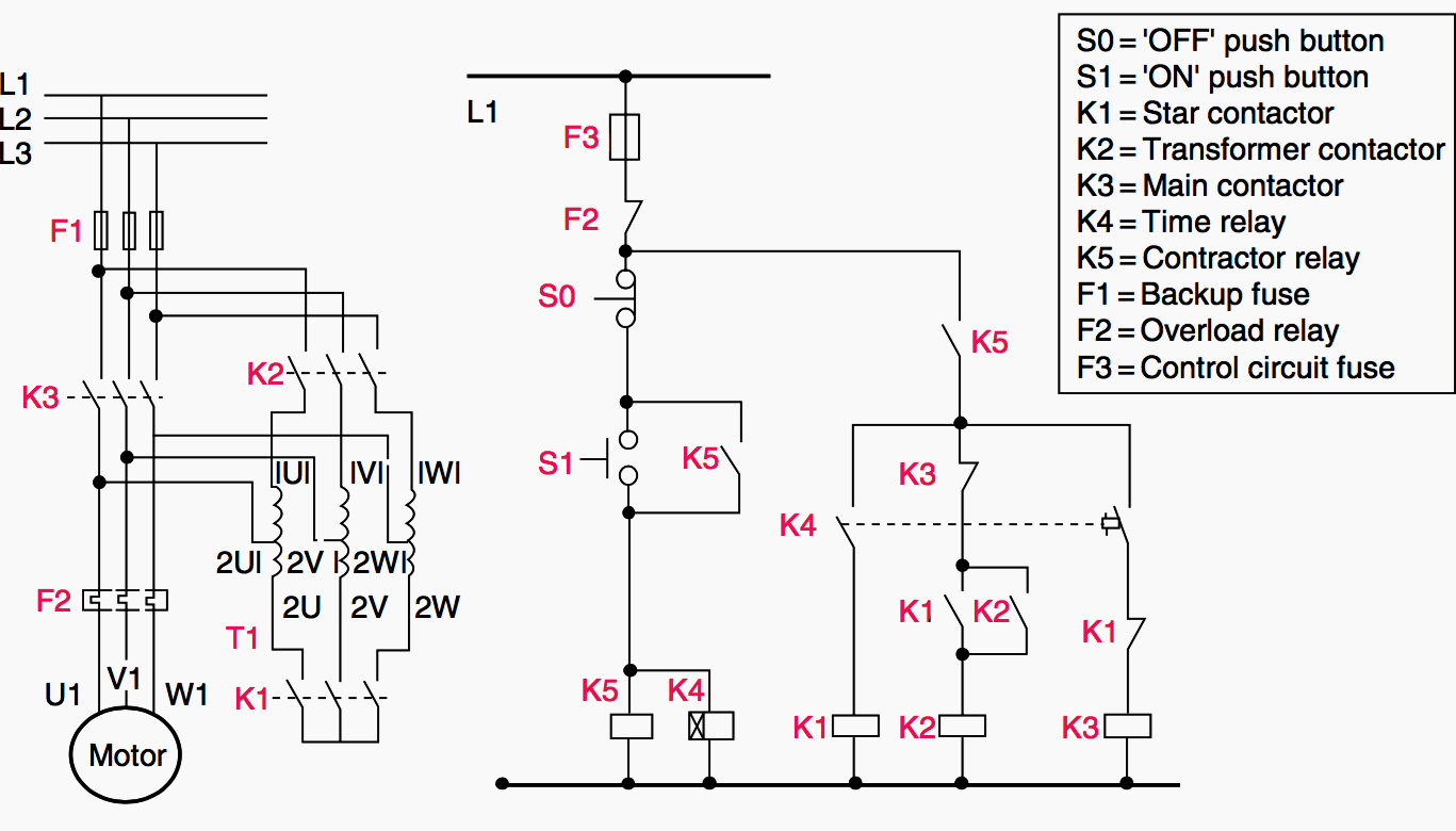
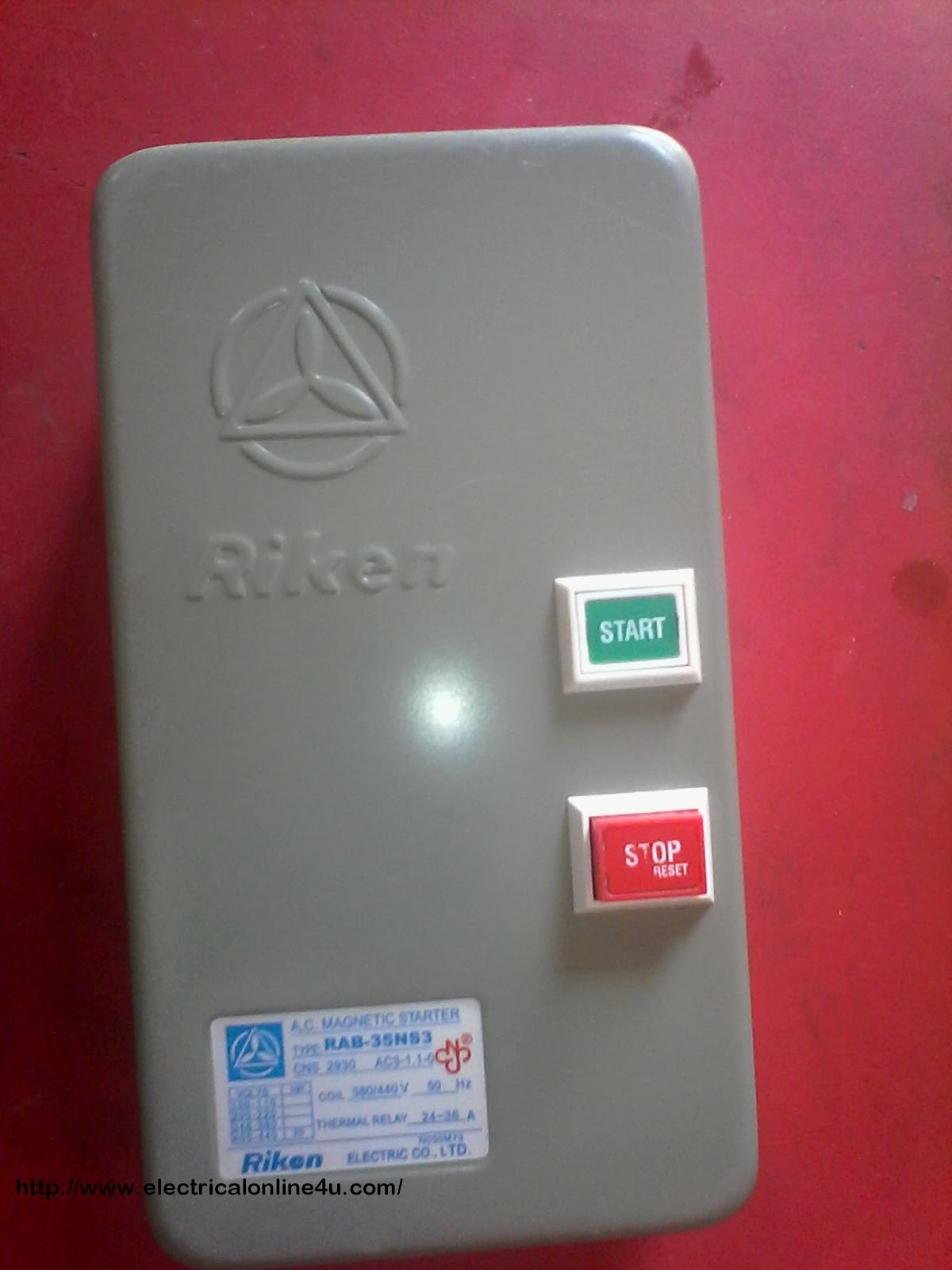
When you push the green no button it will apply 208v across the coil the a1 a2 terminals which will pull in the no contacts and also operate the no aux set which will then maintain power to the coil and latch the contactor so you can let go of the button. I am here with giving you a vfd start stop wiring diagram for running a vfd through panel board push button and keypad of the vfd it is called hmi.

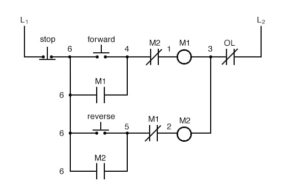
Troubleshooting Three Basic Hardwired Control Circuits Used
Contactor push button diagram. The may be 2 or more sets of output contacts identified. Contactor explained in hindi contactor wiring diagram contactor no nc working electrical dost duration. Releasing f normally open no contacts close forward f fast. These contacts also may be shown as a drawing of a line from 1. For push button control stations 5 explanation of symbols momentary contact push button auxiliary contacts operate when operating coil of contactor. Depressing button opens and parent switch does.
Vfd is a short form of variable frequency drive or variable voltage variable frequency drivethe vfds are working based on changing the input frequency and input voltage of the motor we can change the speed of the. C ontactor buttons i know these images help you very mush in contactor wiring or contactor instillation but you can not learn completely with out a diagram. Vfd start stop wiring diagram. The manufacturer information will identify the 2 input pins for 120 volts ac control. Study the contactor manufacturer information. Contactor wiring with start stop push button.
In this casem main line s slow closes lower contacts. Nc push button we use for switching off the motor and no push button for switching on the electric circuit or 3 phase motor. When you push the red it will break the coils return to neutral no current will. These contacts may be indicated on the label as normally open no and normally closed nc.


