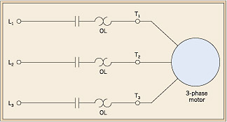
Typical wiring diagrams r t2 l1 t1 l2 t1 t2 motor. Manual starters and switches selection guide catalog 2510ct9701r0116 2016 class 2510 2511 2512 2601 contents.

Manual Motor Starter Switch Wiring Diagram Wiring Diagrams
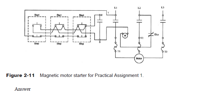
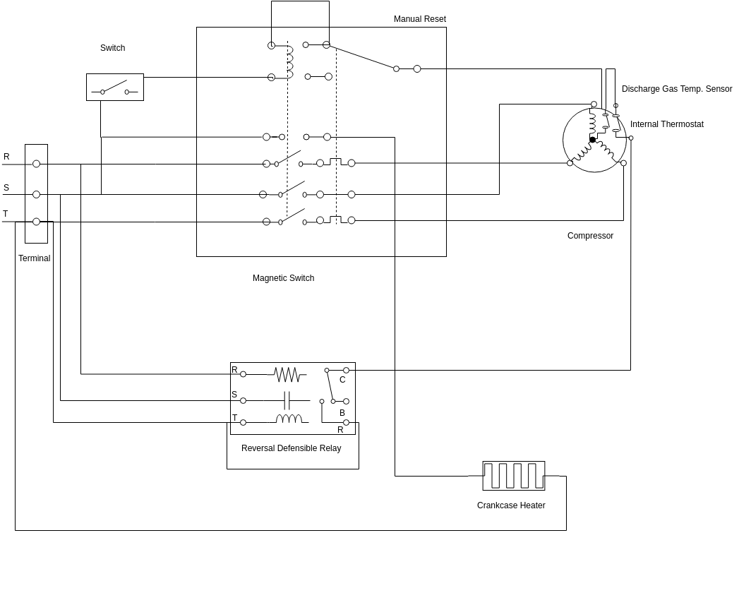
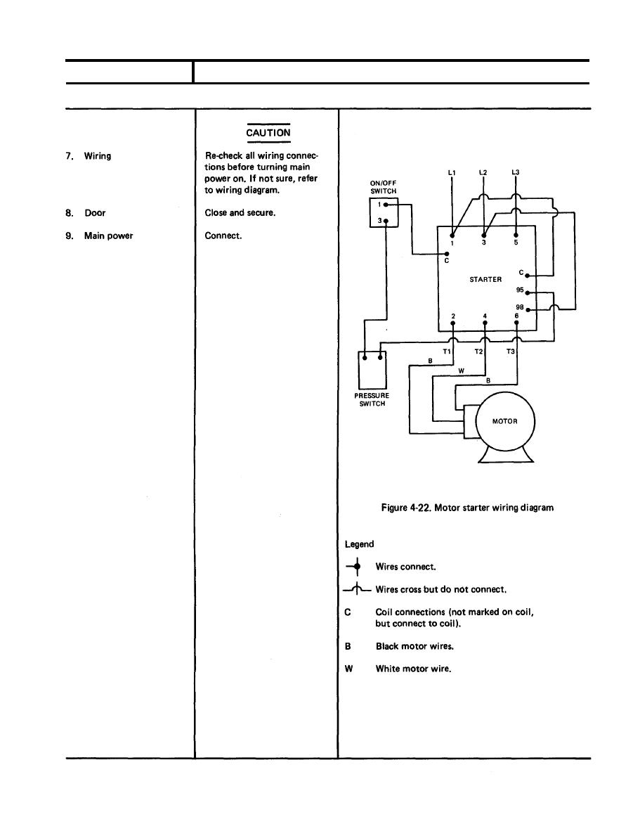
Manual motor starter wiring diagram. A wiring diagram gives the necessary information for actually wiring up a group of control devices or for physically tracing wires when trouble shooting is. Unit so that the markings face the front of the starter. 3ph starter3ph motor line voltage control three phase 3ph motor starter controlling a three phase motor rev 08 aug 2006 the above wiring diagram assumes your magnetic starter has a 240v coil. Square d manual motor starter wiring diagram trusted wiring diagrams exactly whats wiring diagram. Each part should be placed and linked to different parts in specific way. Signs that represent the elements in the circuit and lines.
Each part should be placed and connected with different parts in specific manner. Square d motor starters wiring diagram sq d motor starter wiring diagram square d 3 phase motor starter wiring diagram square d 8536 motor starter wiring diagram every electric structure is composed of various distinct pieces. Variety of square d manual motor starter wiring diagram. A wiring diagram is a simplified traditional pictorial depiction of an electric circuit. The following diagram depicts 3 phase non reversing motor control with 24 vdc control voltage and manual operation. Ac manual starters and manual motor starting switches 12 class 2510 12 class 2511 and 2512 13 2 speed ac manual starters and iec motor protectors.
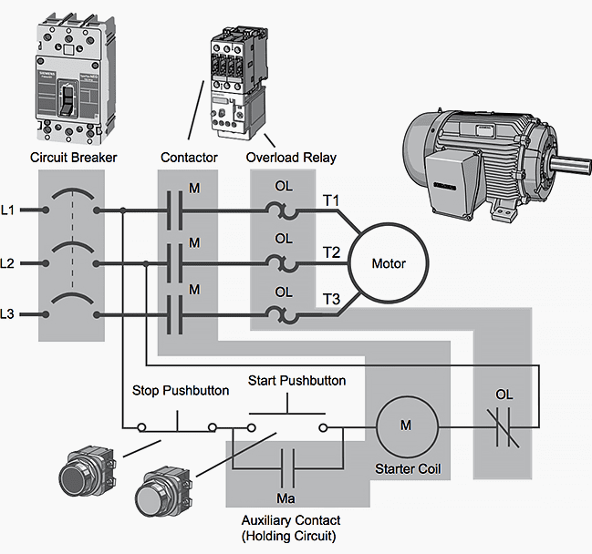
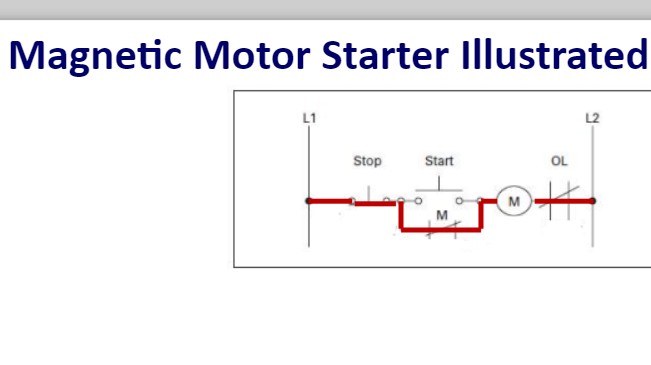
Basic wiring for motor contol circuitry of a starter two wire control two wire control circuits or low voltage release one of the common control wiring circuits used is known as two wire or low voltage release lvr. Wiring diagram book a1 15 b1 b2 16 18 b3 a2 b1 b3 15 supply voltage 16 18 l m h 2 levels b2 l1 f u 1 460 v f u 2 l2 l3 gnd h1 h3 h2 h4 f u 3 x1a f u 4 f u 5 x2a r power on optional x1 x2115 v. Otherwise the structure will not function as it ought to be. It utilizes a main tained contact type of pilot device such as a thermostat float switch or presence sensor. A wiring diagram is a type of schematic which uses abstract photographic symbols to show all the affiliations of elements in a system. Wiring diagrams bulletin 609 manual starters are operated by start.
Honda gx390 electric start wiring diagram honda gx390 electric start wiring diagram every electric arrangement consists of various diverse parts. Circuitry layouts are made up of two points. It shows the elements of the circuit as simplified forms and also the power as well as signal connections between the devices. If not the structure wont work as it ought to be. We will use a contactor an auxiliary contact block an overload relay a normally open start pushbutton a normally closed stop pushbutton and a power supply with a fuse. Two speed manual motor starter is designed for starting protecting small single phase two speed ac fan motors.
If you have a 120v coil instead of running a line from coil overload l2 you must run coil overload neutral.
