The code behind this is pretty simple. 4 channel remote control circuit diagram ic 4017 tsop.
Details About 16 Channel Dc 12v Android Phone Bluetooth Control Relay Switch Module Smart Home
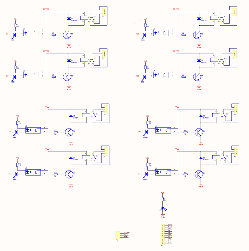
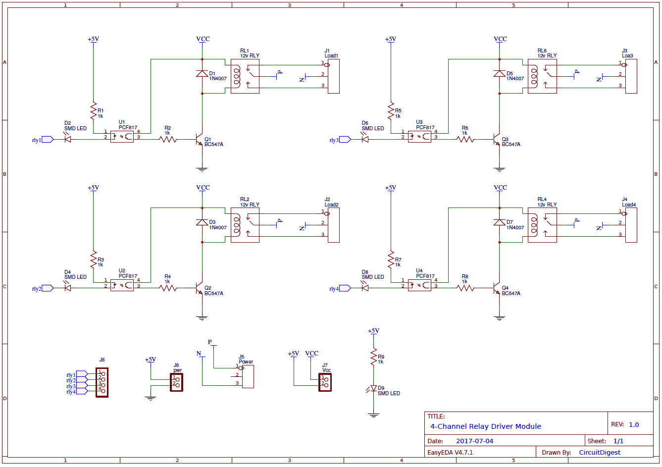
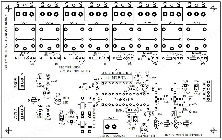
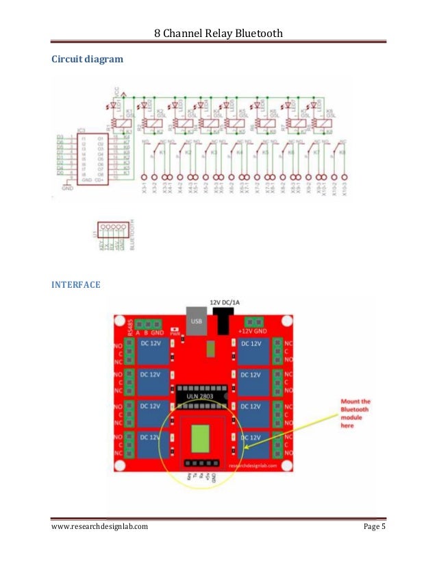
Bluetooth 8 channel relay control circuit diagram. Below given is relay driver circuit to build your own relay module. Then follow the below steps and images. Dc 12v 16 channel bluetooth relay board wireless remote control switch for android phones with bluetooth functions httpswwwbanggoodincustlinkvkd3ny. 5vdc dpdt relay 4 nos 5 bc 547b transistor 4nos. Wiring bluetooth hc06 in 8 channel relay with android arduino microcontroller another guide how to wire the hco6 and 4 channel relay for switching the hc06 modules uses bluecore is a single chip radio and baseband ic for bluetooth 24ghz system including enhance data rates edr to 3mbps. 2020 popular bluetooth control switch relay switch iot relay mobile phone relay trends in home improvement relays consumer electronics remote controls with bluetooth relay switch and bluetooth control switch relay switch iot relay mobile phone relay.
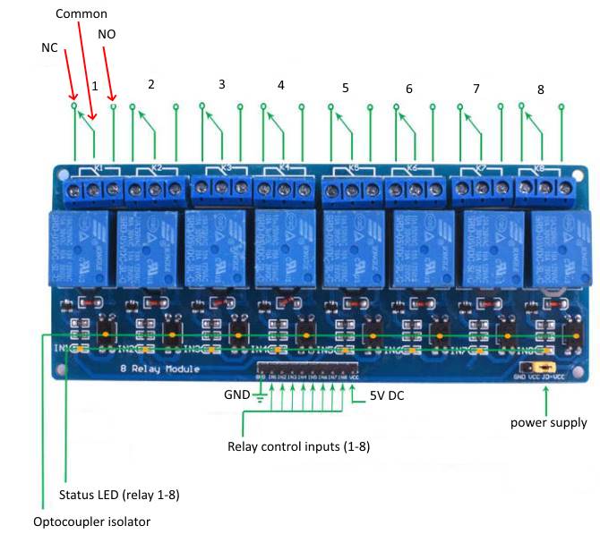
An ac bulb is used for demonstration. Circuit diagram and working. We have connected transistor base to arduino pin a0 through a 1k resistor. If the received data is the character 1 the relay will be triggered and turned on and if the received data is the character 0 the relay will be turned off. Bluetooth control fan speed and light from smartphone. This 8 channel relay module can adopt most common range of microcontrollers such as arduino raspberry pi avr pic arm with digital outputs to control larger loads devices like ac or dc motors electromagnets soleniod incandescent light bulbs actuators and any another devices that you want to drive with in the relay.
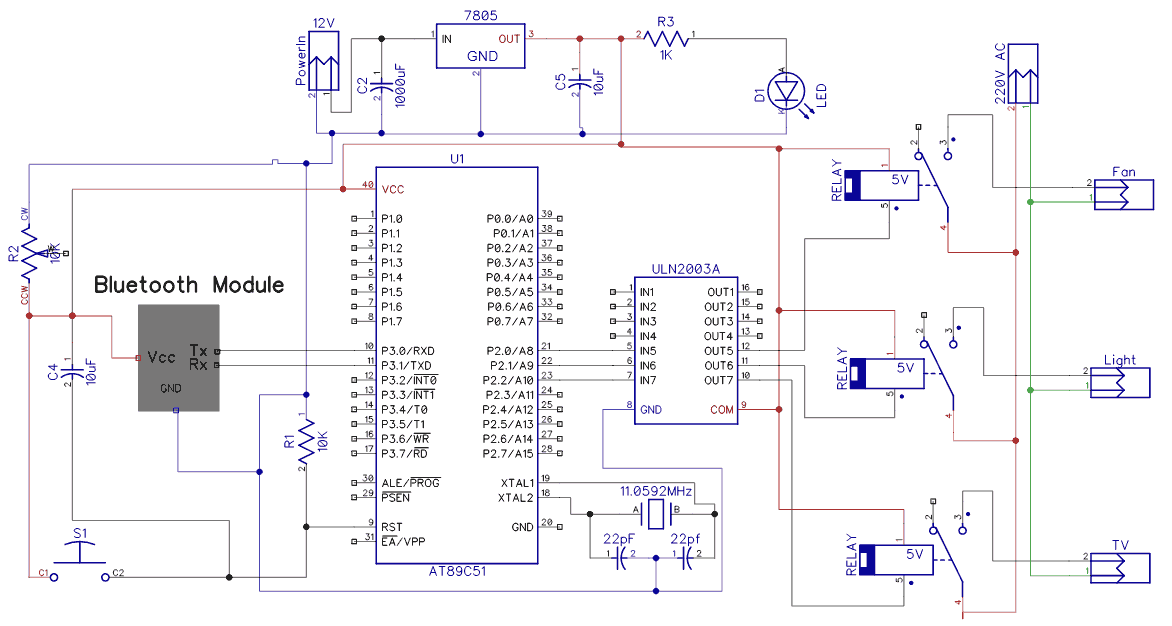
When the 8 channel bluetooth relay module is powerup for the first time a red ledled1 will toggle at 1 hz in the board which means the module is discoverable and waiting for a connection. The bluetooth module receives data from the paired android smartwatch and triggers the relay based on the received data. While we used a single relay in the example you can expand the use case with an optocoupler 8 channel relay. For more details please refer the the csrbc417 datasheet. In this arduino relay control circuit we have used arduino to control the relay via a bc547 transistor. To keep things simple we have used a simple bluetooth app that allows you to control only a single load but in case you wish to control more devices you can use a use a more sophisticated bluetooth control app or write your own.
Go to bluetooth devicescontrol panelhardware and sounddevices and printersbluetooth devices on your pc.


