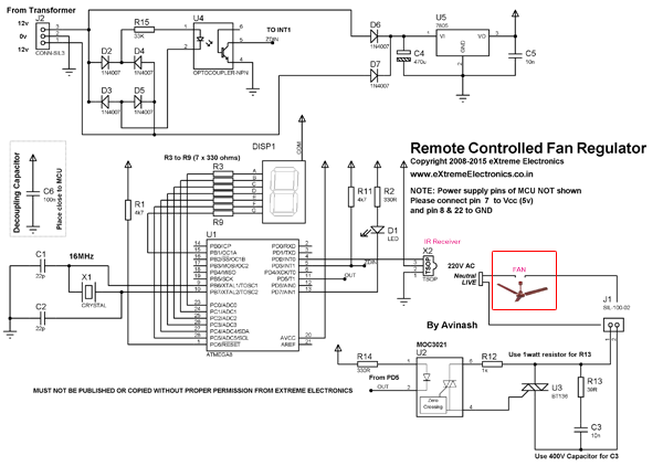
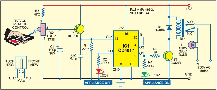
Before wiring the circuit make sure that the carrier frequency of the tv remote you have is 38 khzfor that wire the sensor part only point your remote to the tsop1738 and press any switchif out put of tsop1738 goes low them ok your remote is of 38khz typenothing to worry almost all tv remote are of this type. If replacing a manual 6 position rotary wall switch with the cooler controlleryour old manual 6 position.
Quadcopter Remote Control Circuit Without Mcu Homemade
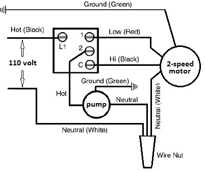
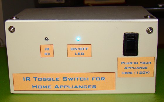
Cooler remote control circuit diagram. Check the room air cooler wiring diagram 2room air cooler wiring diagram 2 with capacitor marking and installation room air cooler wiring diagram 1 click image to enlarge. Room air cooler wiring diagram 1 note. A compressor condenser fan motor and evaporator fan motor. The circuit presented serves as a remote control switch. Position all wiring into junction box. Chmmcp44 ic interior grill cover mcp44mcp44emcp59.
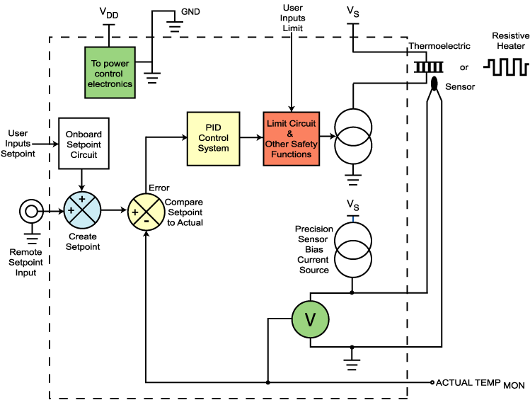
Basically it works on the principle of thermo electric effect opposite of seebeck effect where a potential difference is used for making or producing hot and cold temperatures over the two ends of a dissimilar metal assembly. This circuit is built using ic cd 4017. All are carefully cross referenced into a wide range of categories. This site is a vital resource for engineers hobbyists. First we need to know what loads there are to be controlled. By this switch you can on or oof fan cooler bulb and any electricity device.
Make sure not to miss these resources for. Remote control 8 module square switch board for 6 lights and 2 fans http. An electrical wiring diagram can be as simple as a diagram showing how to install a new switch in your hallway or as complex as the complete electrical blueprint for your new home or home improvement project. Use wire nuts supplied. This site includes a collection of circuits designed by jatinder khatter founder of the website. A peltier device has two terminals in the form of wire ends which requires to be connected across a voltage source rich in current content.
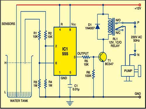
Chm72957 control module wremote for. With circuit breaker turned off connect the thermostat wires as shown within the electrical diagram. A 12 volt relay is used in this circuit which acts as a switch. The image on the left shows a small split system for a walk in cooler with 3 electrical devices. Chmmcp44 ec retail exterior winter cover for. Lets add a basic control system to a refrigeration system.
Part no description price. Cooler moter wiring or regulater wiring. This link is helpful as a homeowner do it yourself electrical wiring. List of all the electrical components used in this circuit given below. These categories include amplifiers power supplies solar hobby circuits etc. Connection of fan circuit diagram with capacitor table fan affiliate.
Mount thermostat to junction box using the screws provided.


