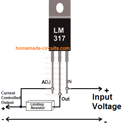
The circuit also incorporates an electronic output current limiter that effectively controls the output current from a few milliamperes 2 ma to the maximum output of three amperes that the circuit can deliver. The ic lm338 is configured as the current controller and as the circuit breaker module.
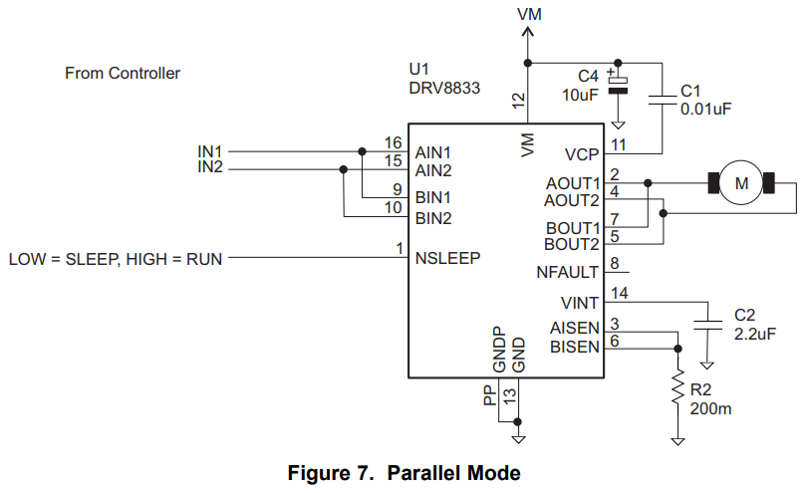
Drv8833 About Motor Current Control By Current Detection
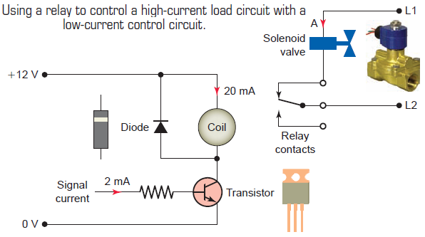
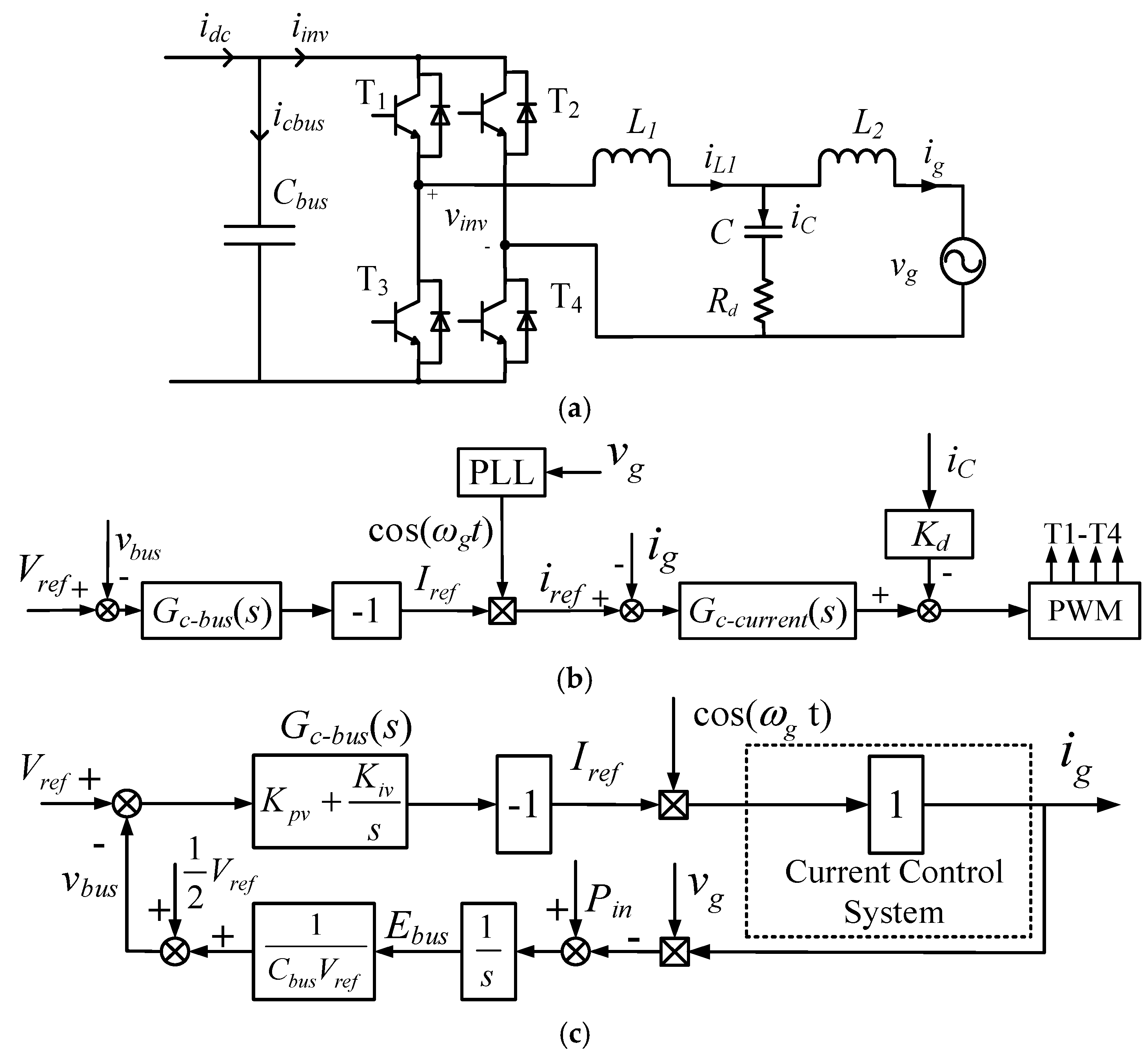
Current control circuit diagram. Current control circuit for led. 2there is no response for current control. This schematic shows both the control circuit and the motor circuit. Current source inverter control. See more ideas about electrical diagram electrical circuit diagram electrical engineering. A very common form of latch circuit is the simple start stop relay circuit used for motor controls whereby a pair of momentary contact pushbutton switches control the operation of an electric motor.
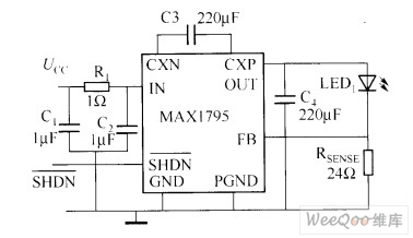
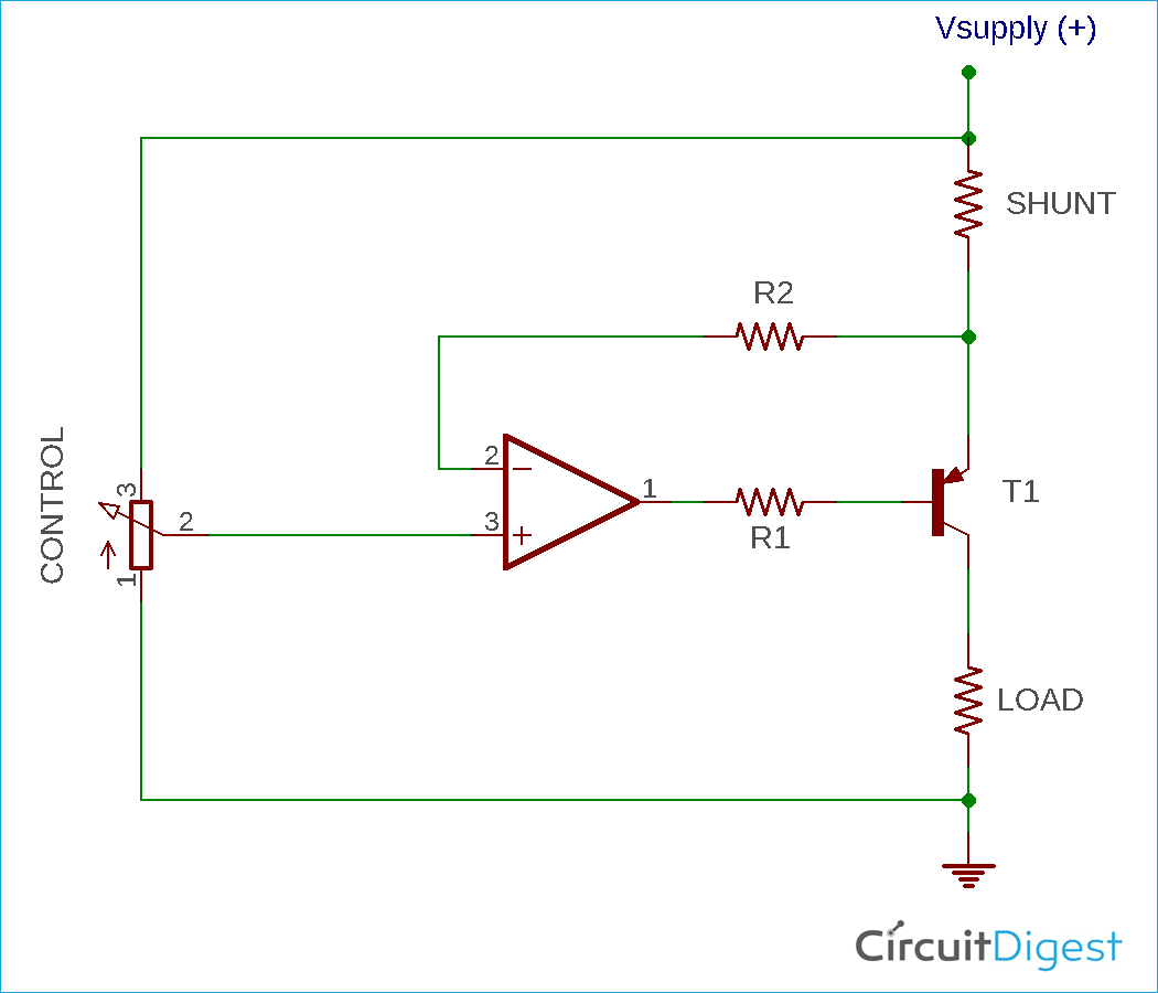
Feb 5 2020 explore elects agass board electrical diagram on pinterest. This is a high quality power supply with a continuously variable stabilised output adjustable at any value between 0 and 30vdc. I have checked the circuit n times as per your circuit. 2ohm3w for 300ma output 3when there was overloading 24v700ma dc motor r2 120ohms burned alongwith t2not able to confirm whether it was due to overload or the growing hotness of as mentioned in point no. The op amp in this circuit u1a is in a closed loop because the negative input and output are connected together through q3 and so the op amp will attempt to keep the and. Share on tumblr this circuit constructed to derive 1w power led array the ic max16832 is a step down constant current high brightness led driver.
Figure 914 shows a start stop push button circuit. Current control circuit for led. Schematic diagrams do not always show both control and motor connections. You can design a led bulbs led illumination applications or other power led based lighting application by using max16832. Many schematic diagrams show only the control circuit. The first circuit to be discussed is a basic control circuit used throughout industry.
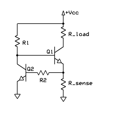
Circuit diagram this circuit constructed with self pwm oscillation circuit and option for external pwm input hence you can. In this particular case i show a low voltage control circuit and a 3 phase higher voltage motor. You can design a led bulbs led illumination applications or other power led based lighting application by using max16832. This circuit constructed to derive 1w power led array the ic max16832 is a step down constant current high brightness led driver. Referring to the circuit diagram we see that the entire circuit is wired around the ic lm301 which forms the control circuit for executing the trip off actions. The output of the op amp is connected to the base of a power transistor ignoring the darlington pair which controls how much current can flow through the circuit.
Using lm338 as a regulator and opamp as the comparator. The voltage source is connected in series with a large value of inductance l d and this named the circuit as the current sourcethe circuit diagram of the current source inverter fed induction motor drive is shown in the below figure.
Gallery of Current Control Circuit Diagram