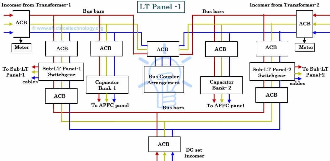
2 or more dg are sets may be used parallel in order to share the total load of system. Billing can be reduced almost to 40.

Dg Panel Wiring Diagram
Dg panel wiring diagram. C13n6h c17n6h c20n6h and c20n6hc models wiring diagram hdkat hdkau and hdkav wiring diagram. The bek3 controller is able to work from 5 up to 36vdc. In order to improve power factor so that billing is reduced by avoid penalty from governments through introducing kvars into power. Gps 5600a wiring. In synchronization 2 or more dg sets are working in parallel and their supply transferred to main load via a single bus. Related electrical wiring tutorial.
21l srss and mv petrol engines. Dg supply in the event of utility supply failurein this project workan amf arrangement is fabricated wired up interfaced with laboratory three phase alternator and was tested for different sequences. A dg synch panel is an electrical circuit which controls the functionality of dg sets. An amf panel equipped with bek3 is designed to work with the power generator engine battery. Why we use apfc panel. Three phase dol starter control overload indicator power wiring diagram duration.
The connected load details in the college. 200300400 series wiring diagram pts8csi nm diesel wiring diagram powertech diesel wiring diagram powertech with ecu 63 control module wiring diagram. Ltd noida uttar pradesh india. Amf control panel circuit diagram pdf description. Turbodiesel turbocharger cooling fan. Connecting the current transformers after the mains and generator changeover will allow you to read and monitor the current when the load is connected to the power utility.
Part no2 generator automatic panel wiring duration. Ups inverter wiring diagram with auto manual changeover switch system. Trader and service provider of dg synchronization dg load management parallel dg operation auto dg on off fuel saving in dg and auto mains failure panel offered by sgs industrial controls solutions pvt. The above illustrated diesel generator control panel wiring diagram is the typical connection wiring diagram of the bek3 automatic mains failure controller. Now according to the below ups connection diagram connect an extra wire phase to those appliances where we have already connected phase and neutral wires from power house db ie two wire as phase live as shown in the below fig. Also a real time amf circuit was studied for interlocks and various sequences of operation.
19l sp and dg petrol engines. Volkswagen transporter 1980 1992 aka t3 t25 type 25 vanagon factory wiring diagrams pdf second battery cut out relay. 125 kva dg set gurgaon india. Manuals info wiring diagrams. 16l cs ky and jx diesel engines. The controller will guarantee remote control monitoring and functionalities when utility power is outside limits.
Propak12 and propak16 wiring diagram.


