Find the correct breaker and turn it off. This outlet is commonly used for a heavy load such as a large air conditioner.
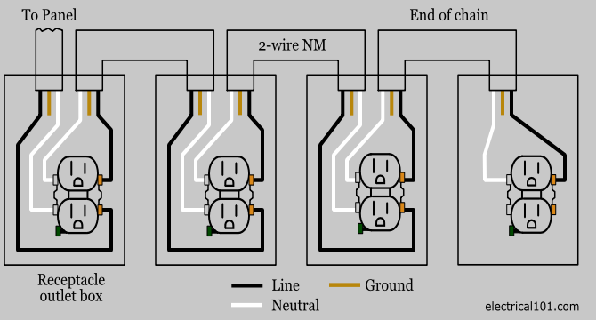
Receptacle Wiring Diagram Wiring Diagram
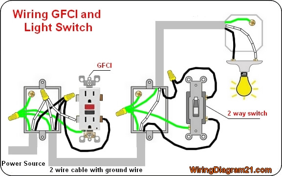
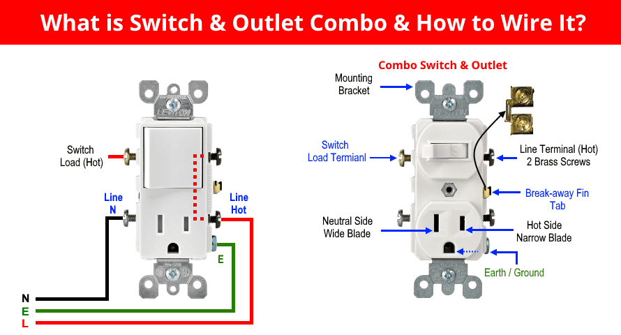
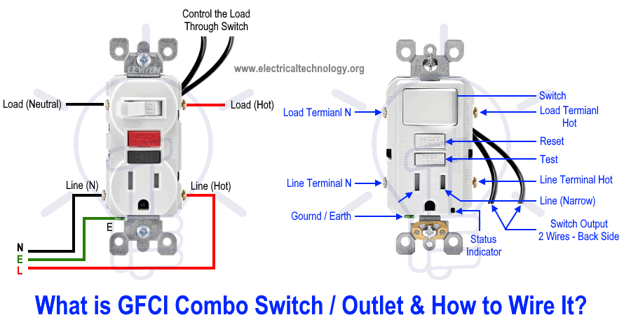
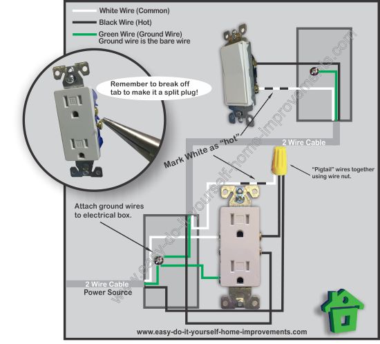
Diagram of electrical outlet. The outlet should be wired to a dedicated 20 amp240 volt circuit breaker in the service panel using 122 awg cable. Turn off the power at the main panel. These electrical wiring diagrams show typical connections. In the diagram below a 2 wire nm cable supplies line voltage from the electrical panel to the first receptacle outlet box. Once youve determined the electrical outlet to use as a power source and shut it off use an electronic stud finder to locate the studs on both sides. Wiring diagram of a switched electrical receptacle outlet and an unswitched electrical receptacle outlet with the power entering the switched outlet electrical box from the circuit breaker panel.
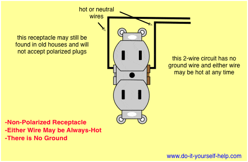
Wiring a 20 amp 240 volt appliance receptacle. Shut off the electrical outlet. Steps to take when wiring the electrical outletreceptacle. With this wiring both the black and white wires are used to carry 120 volts each and the white wire is wrapped with electrical tape to label it hot. The black wire line and white neutral connect to the receptacle terminals and another 2 wire nm that travels to the next receptacle. You can put your new outlet anywhere between these two studs.
How to wire an electrical outlet wiring diagram wiring an electrical outlet receptacle is quite an easy jobif you are fixing more than one outlet the wiring can be done in parallel or in series. The single pole switch has a neutral conductor for future electronic controls such as a timer or a wifi switch. This repeats until the end of the chain. The diagram below shows the power entering the circuit at the grounded outlet box location then sending power up to the switch and a switched leg back down to the outlet.


