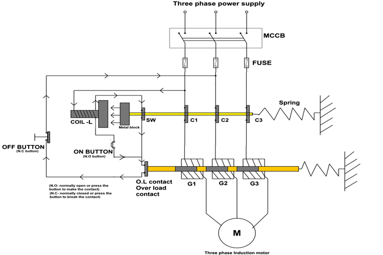
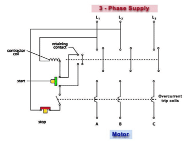
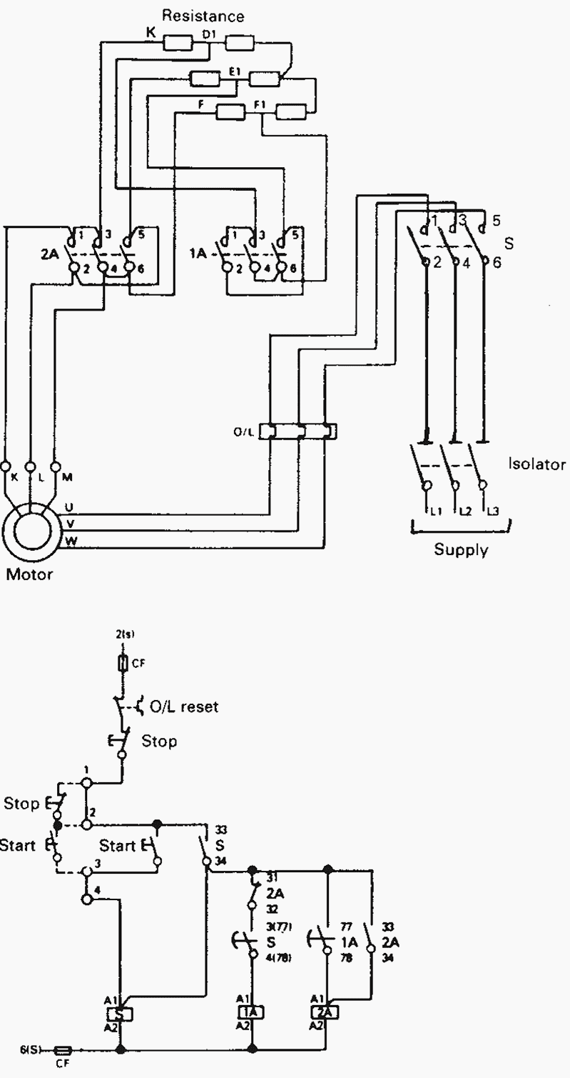
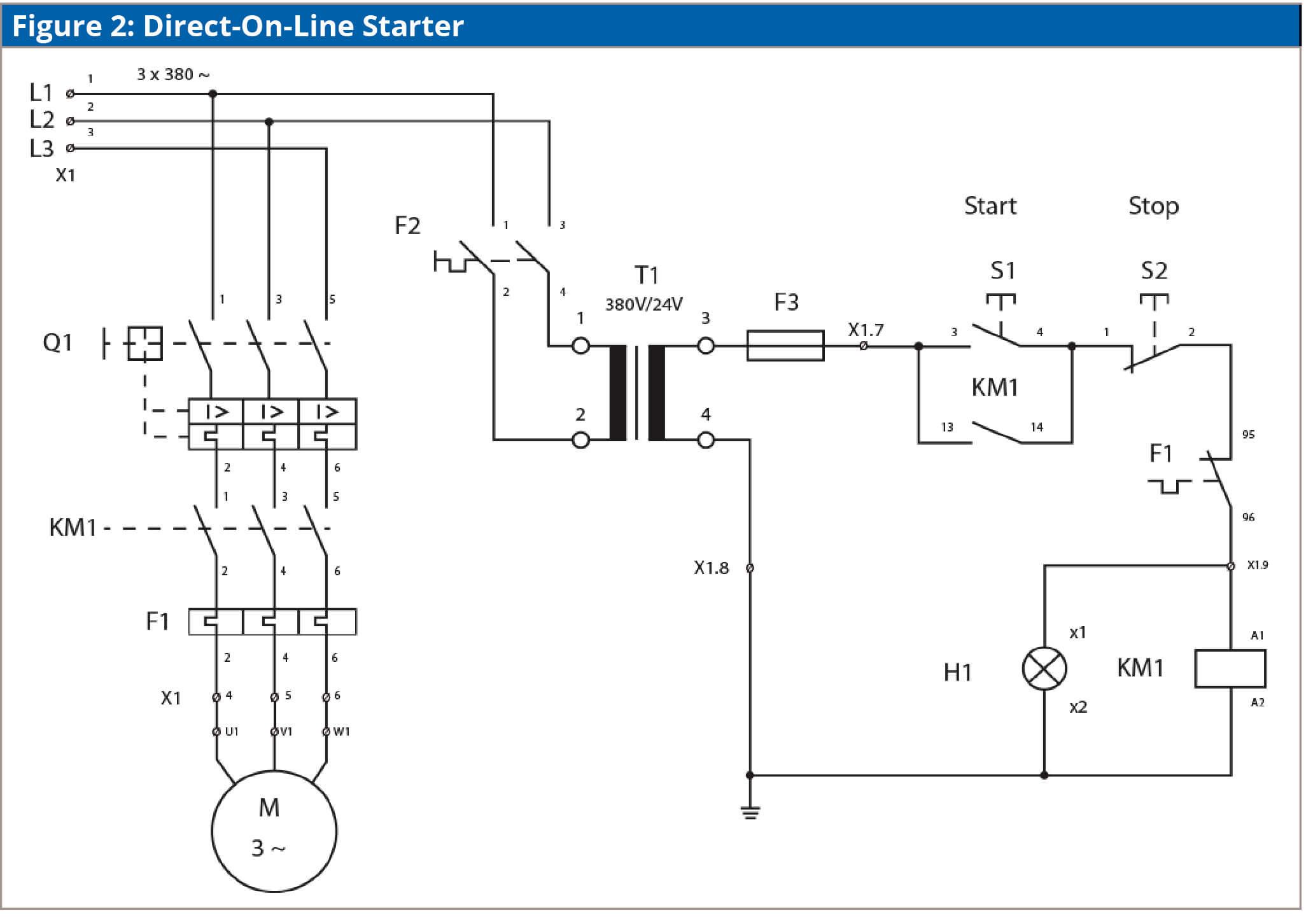
Dol direct online starter wiring diagram. A direct online starter consits of two buttons a green button for starting and a red for stopping purpose of the motor.

Tb 0766 Wiring Diagram Dol Starter S Plan Wiring Diagram
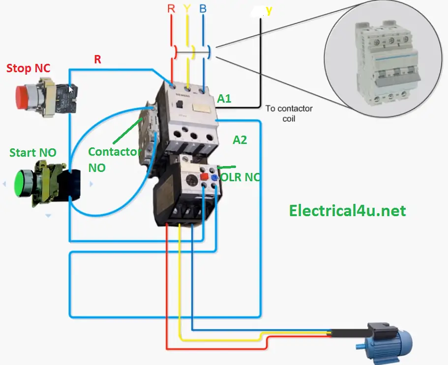
Direct online starter wiring diagram. The dol starter comprises of an mccb or circuit breaker contactor and an overload relay for protection. The ryb is the three phase 380 volts supply. The wiring diagram for a dol stater is shown below. The main heart of dol starter is relay coil. The wiring of direct on line control circuit starter is following. Also the earth.
The coil of the contactor is 380 vac. Dol starter wiring diagram direct online starter dol starter wiring diagram yes this post is about to understand the 3 phase motor dol starter wiring connection. These two buttons ie. Normally it gets one phase constant from incoming supply voltage a1when coil gets second phase relay coil energizes and magnet of contactor produce electromagnetic field and due to this. The contactor connection with thermal overload relay and the motor connection with overload relay is shown. The direct online or dol starter employs full voltage or across the line starting technique where the motor is directly connected to full voltage through mccb or circuit breaker and relays for overload protection.
Which is easy made my a 3 pole or 4 pole mcb miniature circuit breaker or mccb molded circuit. I hope this three phase dol starter wiring or 3 phase motor wiring with direct online starter diagram help you. Green and red or start and stop buttons. And the normally open and normally close push button shown. Generally the direct online starter working can be done in two different stages namely dol starter control circuit and dol starter power circuit. Three phase and single phase.
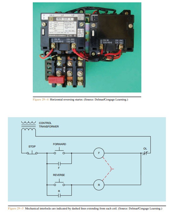
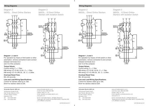
Three phase motor control and design power circuit and installation. Wiring diagram of dol starter. Mccb wiring diagram for 3 pole 4 pole. And if you learn something from the diagram then also share this post. This diagram illustrates possible wiring using a tesys d lc1d contactor and tesys lrd overload lrd and stop control is assumed to be by operation of the stop button on the overload. For small load three phase motor the common controlling device is dol starter.
Schematic and circuit diagram. Working principle of dol starter. If a starter incorporating a tesys k series contactor lc1k is used then the connections between 9514 and 96a2 are made internally. In the above dol starter diagram. The connection of contactor can be done among relay coil supply voltage as well as thermal overload. The dol starter joints the 3 phase main wiring with the induction motor namely l1 l2 and l3 when the start switch is pressed.
Direct on line starter wiring diagram. Direct on line starter. Dol starter control diagram three phase. The l1 contactor is connected from normally open no to r phase using mccb. Now if you have any question then use can use the below comments section. The 3 phase dol starter wiring diagram is shown below.
This is why such a starter is used with induction motors rated below 5 hp.
