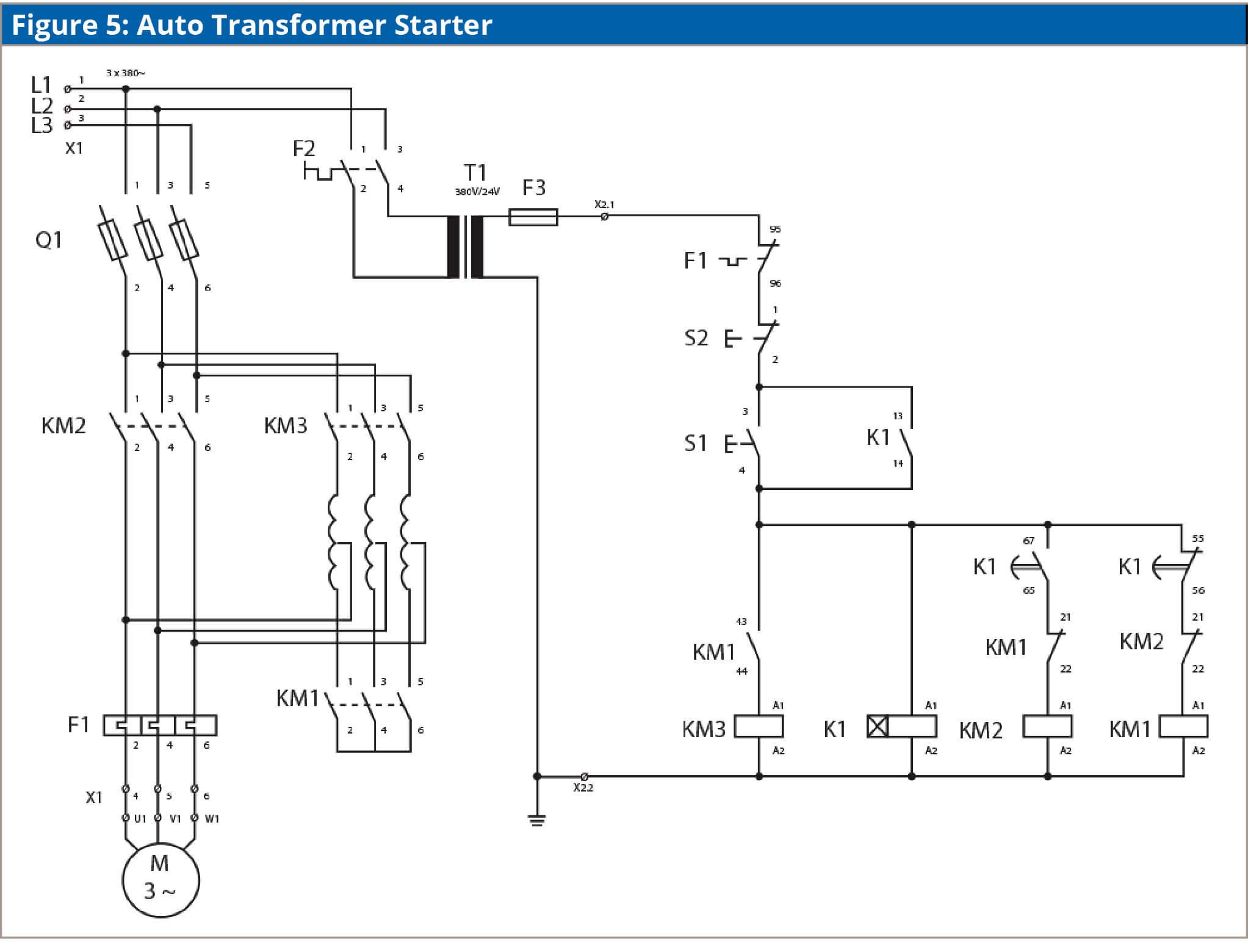
Dol direct online starter. In case of small rating motors having less than 05hp motors.
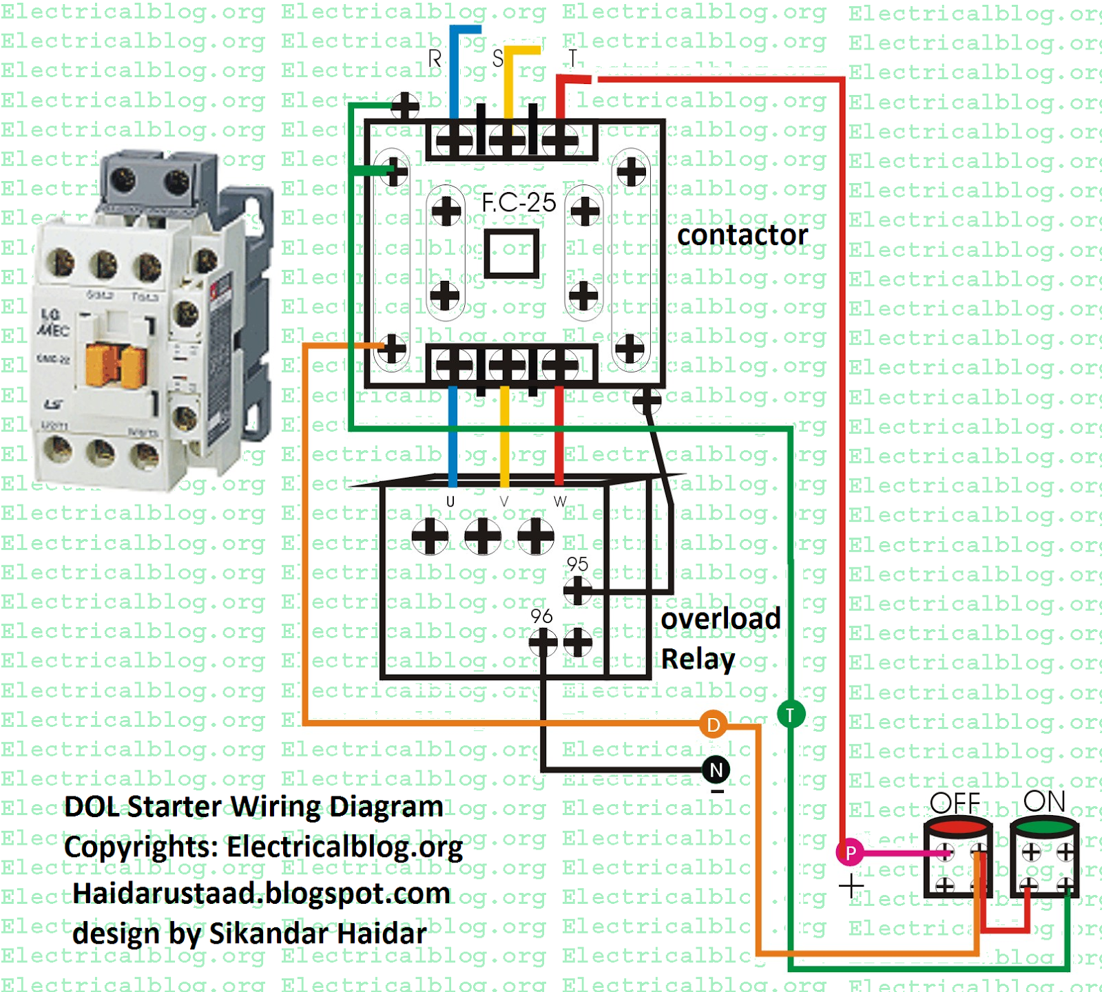
Direct Online Starter Wiring Diagram Diagram Base Website
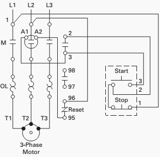
Dol electrical diagram. The circuit breaker is used for protection against short circuits while the overload relay protects the motor from overloading. The connection of contactor can be done among relay coil supply voltage as well as thermal overload. This may cause an electrical problem with the supply or it may cause a mechanical problem with the driven load. The wiring of direct on line control circuit starter is following. About this video dosto aaj. In order to avoid direct switching dol starters are implemented.
All connection i shown with complete guide. Dol starter control diagram three phase. So this will be inconvenient for the users of the supply line always experience a voltage drop when starting a motor. During normal condition it acts as a switch. Ryb electrical a dol starter is a direct on line motor starter. A direct online starter consits of two buttons a green button for starting and a red for stopping purpose of the motor.
But if this motor is not a high power one it does not affect much. In this article we will study about dol starter control diagram. Direct online starter in hindi control and power wiring diagram of motor starter electrical dost i am aayush sharma welcome to our youtube channel electrical dost. Dol starter connection dol starter control. Dol starter motor connection. The dol starter comprises of an mccb or circuit breaker contactor and an overload relay for protection.
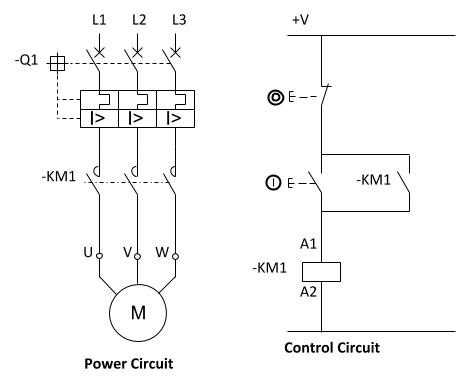
In this post we are going to know the details of each part of dol starter diagramall parts of the dol starter power circuit diagram and control circuit diagram are explaineddirect online starter or dol starter is very useful and commonly used ac starterdol starters are mainly used with up to 5 hp motors. The l1 contactor is connected from normally open no to r phase using mccb. In the below dol starter wiring diagram i shown a molded case circuit breaker a magnetic contactor normally open push button normally close push button switch thermal overload relay motor trip indicator and 3 phase motor. Dol starter control diagram. The starting current is not so very high and these motors can withstand starting current without any starters. The dol starter is made of a circuit breaker or mccb or fuse an overload relay and contactor or coil.
The contactor is used for starting and stopping the motor where the green and red buttons are connected. Thus there is no need to reduce the applied voltage to control the starting current. Overloadindicator and power wiring diagram. The wiring diagram for a dol stater is shown below. A direct on line dol or across the line starter is an electrical device used to apply a full three phase line voltage to the electrical motor terminals. In the above three phase dol starter wiring diagram.
Wiring diagram of dol starter.




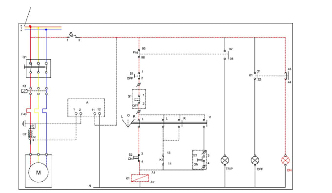


.jpg)


