Collection of prodigy brake controller wiring diagram. Primus iq is a totally proportional electric trailer brake control.
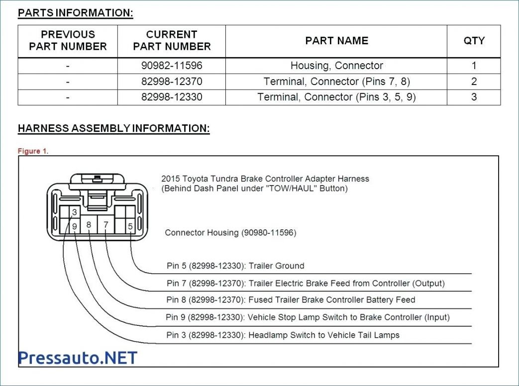
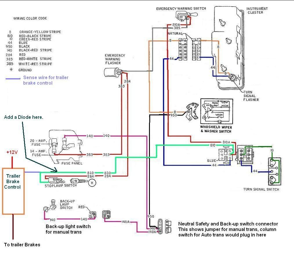
Ef8078 F350 Brake Controller Wiring Diagram Wiring Library
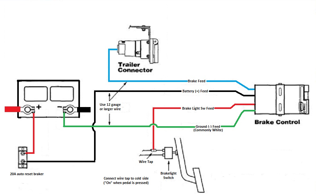
Electric brake controller wiring diagram. In the trailer wiring diagram and connector application chart below use the first 5 pins and ignore the rest. Wiring the 7 way trailer connector and brake controller. If not the arrangement will not function as it ought to be. Each component ought to be set and connected with different parts in particular manner. Auxiliary connection is optional it may be connected to any 12v to 24v constant power source or left unconnected. Break away systems may be added to the service brake circuit.
Keep these instructions with the brake control for future reference. Use the 7 pin connector anyway see below and just leave out the last 2 wires. Primus utilizes the primary sensor technology from. In this guide we cover step by step how to install a brake controller. It shows the elements of the circuit as simplified forms as well as the power and also signal connections between the devices. If your vehicle is not equipped with a plug and play harness you can also splice in wiring for connecting a brake controller.
If your truck has a built in 7 pin socket but you only need 5 of the pins. Read and follow all instructions carefully before wiring brake control. Important facts to remember 1. Wiring harness dkblue trailer brake controller switched outputred fused trailer brake controller battery feedblack brake controller groundlt blue vehicle stop lamp switch to brake controller input brown brake controller illuminationcontroller wires red white blue and blackplease let me know what wires go where. Return to the duplex cable under the hood where the brake wire now white needs to be separated from the 12 volt hot lead black. Electric brake controller wiring diagram.
7 pin trailer wiring diagram with brakes 7 pin flat trailer wiring diagram with brakes 7 pin rv trailer wiring diagram with brakes 7 pin trailer wiring diagram with brakes every electrical arrangement is made up of various different parts. Hard wiring diagram and instructions pdf. Can you get me a wiring diagram for primus iq brake controller. Secure the brake controller into the mounting bracket. The four wires on the brake controller will be connected shortly. The brake control must be installed with a 12 volt negative ground.
A wiring diagram is a simplified traditional photographic depiction of an electrical circuit. Wiring instructions for electronic brake controls pn 4399 rev k generic wiring diagram read this first. Dan tekonsha primus iq trailer brake controller 1 to 3 axles proportional. Elecbrakes is designed to operate 1 to 2 braked axles. Whether your connecting a brake controller or wanting to run 15 30 or 50 amps of additional power hayman reeses plug and play smartclick wiring system makes it easier than ever to fit a range. Installing a brake controller involves disconnecting the vehicle battery mounting the brake controller onto dash and plugging the unit in with a vehicle specific wiring harness.

