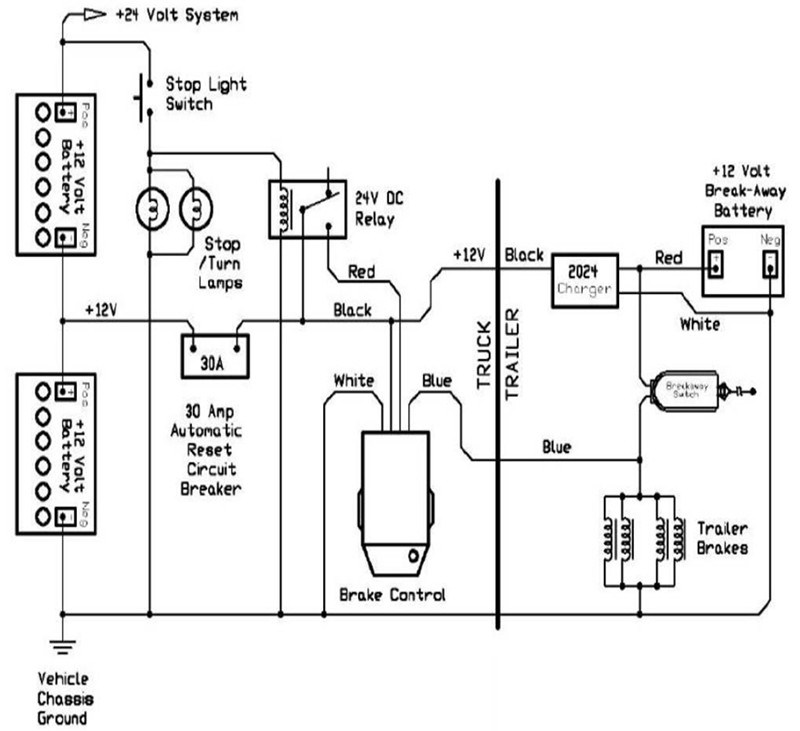
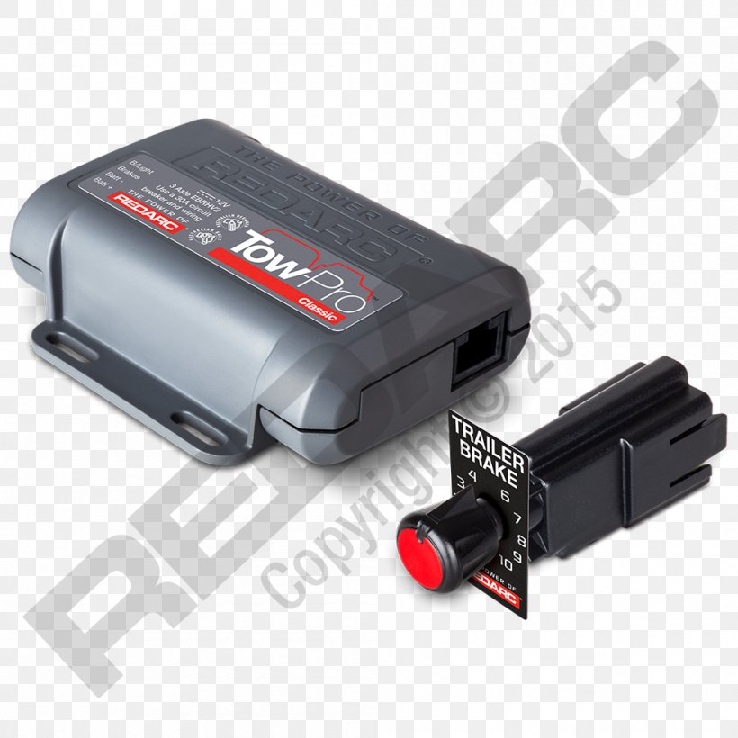
Primus brake controller wiring diagram nov 16 horbar. Collection of prodigy brake controller wiring diagram.
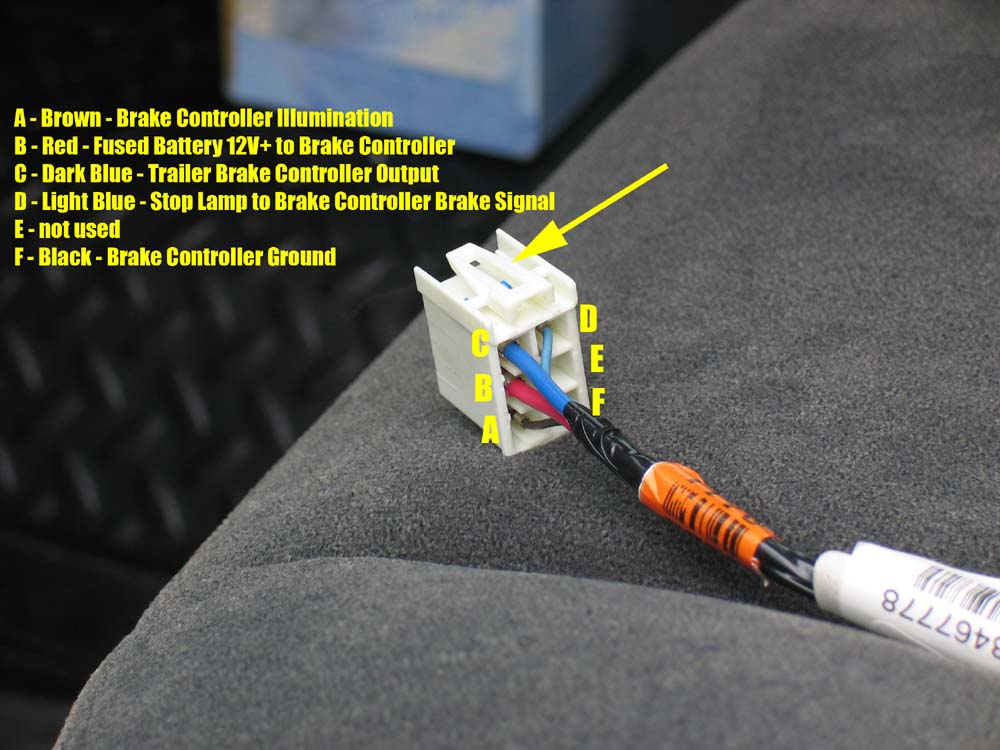
Billavista Com Trailer Brake Controller Tech Article By
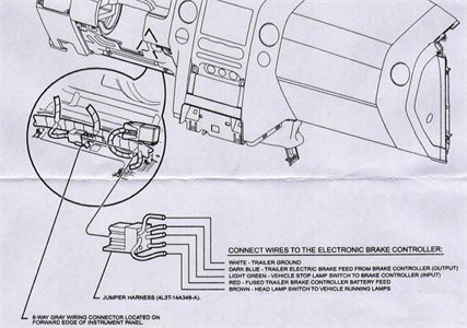
Electric trailer brake controller wiring diagram. Read and follow all instructions carefully before wiring brake control. Following the wiring diagram included with the controller run the blue wire through the firewall and to the rear of the vehicle where it will connect to the trailer connector. Each component ought to be set and connected with different parts in particular manner. If not the arrangement will not function as it ought to be. Wiring instructions for electronic brake controls pn 4399 rev k generic wiring diagram read this first. The service brake circuit must be disconnected from an existing trailer plug.
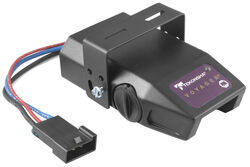
In this guide we cover step by step how to install a brake controller. You almost certainly know already that primus brake controller wiring diagram is among the top issues online. Reese trailer brake controller wiring diagram hayman reese trailer brake controller wiring diagram reese electric brake controller wiring diagram reese pilot trailer brake controller wiring diagram people today comprehend that trailer is a vehicle comprised of very complicated mechanisms. If you do use it then be sure you protect the vehicle electric system from shorts use a fuse or circuit breaker. It shows the elements of the circuit as simplified forms as well as the power and also signal connections between the devices. Wiring the 7 way trailer connector and brake controller.
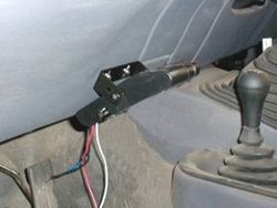
Secure the brake controller into the mounting bracket. It reveals the parts of the circuit as streamlined forms as well as the power and signal connections in between the gadgets. 7 pin trailer wiring diagram with brakes 7 pin flat trailer wiring diagram with brakes 7 pin rv trailer wiring diagram with brakes 7 pin trailer wiring diagram with brakes every electrical arrangement is made up of various different parts. The brake control must be installed with a 12 volt negative ground. Ensure it is sealed off and cannot create a short circuit with any other wire or the chassis. Elecbrakes must be connected to trailer wiring circuits as outlined in the wiring diagram.
A wiring diagram is a streamlined conventional pictorial representation of an electric circuit. This vehicle is designed not just to travel one location to another but also to carry heavy loads. Return to the duplex cable under the hood where the brake wire now white needs to be separated from the 12 volt hot lead black. The four wires on the brake controller will be connected shortly. If your vehicle is not equipped with a plug and play harness you can also splice in wiring for connecting a brake controller. Assortment of electric trailer brake wiring schematic.
Important facts to remember 1. The routing is not on the above trailer wiring diagram because it is optional and different for every trailer. A wiring diagram is a simplified traditional photographic depiction of an electrical circuit. Installing a brake controller involves disconnecting the vehicle battery mounting the brake controller onto dash and plugging the unit in with a vehicle specific wiring harness. Keep these instructions with the brake control for future reference. If you dont need separate power on the trailer just leave that pin out.


