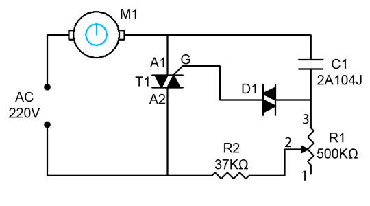
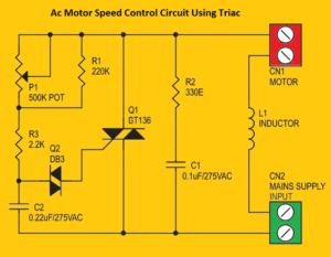
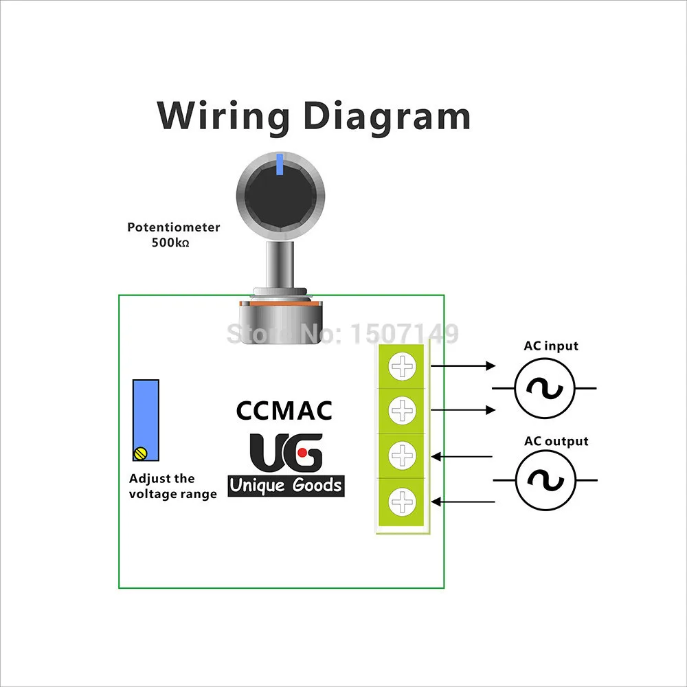
The setting of p1 determines the phase of the trigger pulse that fires the triac. A proper heat sink must be fitted with bt136 triac.
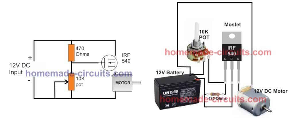
3 Simple Dc Motor Speed Controller Circuits Explained
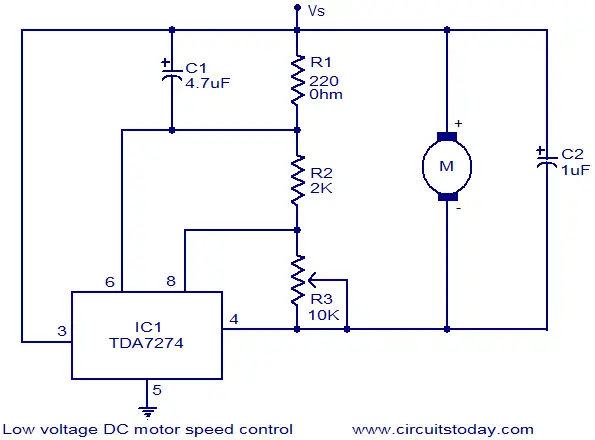
Electric motor speed control circuit diagram. In the engine speed controller any transistors with an operating current of at least 250 ma and a. The speed is controlled through an externally applied varying dc voltage source. So you can only use up to 800watts electric equipment to control. Multi speed 3 phase motor 3 speeds 1 direction power control diagrams one line diagram of simple contactor circuit. In this particular case i show a low voltage control circuit and a 3 phase higher voltage motor. Kindly email me the diagrams for star deltor and direct online for a 3speed 1directon 3ph motor have two of them in a bow cutter.
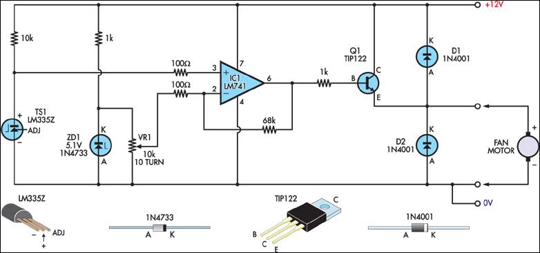
The term esc stands for electronic speed control is an electronic circuit used to change the speed of an electric motor its route and also to perform as a dynamic brake. It is configured for automobile usage with negative terminal of the power supply connected to. 220vac motor speed controller schematic. A very common form of latch circuit is the simple start stop relay circuit used for motor controls whereby a pair of momentary contact pushbutton switches control the operation of an electric motor. Here is a simple dc motor speed controller circuit that can be configured to control the sweep rate of automobiles windscreen wiper. The device is designed to adjust the speed of an electric motor running on alternating current.
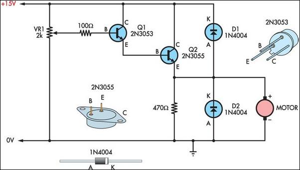
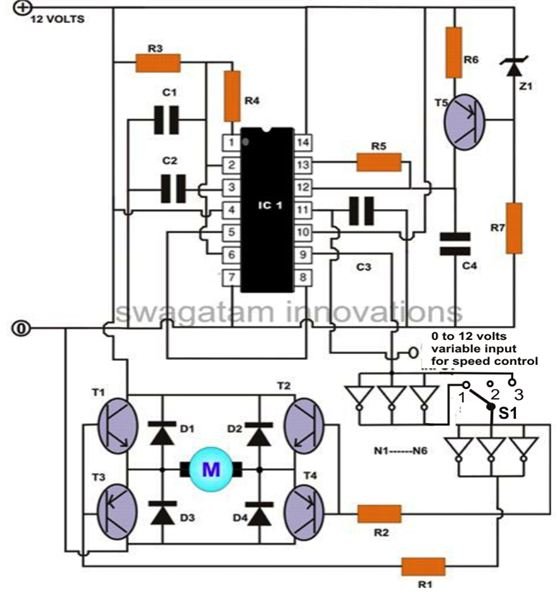
The circuit comprises a timer ne555 ic1 medium power driver transistor bd239 t1 high power switching transistor bd249 t2 and a few other discrete components. It is having the maximum terminal current is 4a. I see 4 wires going to the fieldstator coils. Then check out this outstanding single chip pwm motor speed controller circuit that will give you a complete 360 degrees of continuously varying motor speed control right from zero to maximum. Please help how to go about this. One contactor burnt for high speed and a replced contactor does not engange originally the coils re fed with a nutural and the one i replaced is only working with a phase.
Three phase electrical wiring installation in home iec nec. This circuit is working based on the triac of bt 136. The speed of the motor can be controlled by changing the setting of p1. I am trying to automate the control of an electric drill motor that im taking from a garden variety variable speed drill from harbor freight it has a universal ac motor which i basically undertand and a dpdt switch to reverse direction and a triac citcuit to vary speed. Working of ac motor controller. The circuit incorporates a self stabilizing technique that maintains the speed of the motor even when it is loaded.
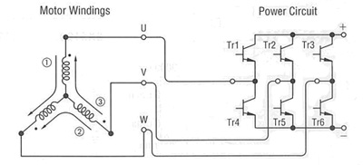
These are frequently used on radio controlled models which are electrically powered with the change most frequently used for brushless motors providing an electronically produced 3 phase electric power low voltage source. Are you fed up with ordinary pwm circuits which do not provide perfect dc motor speed control especially at lower speeds.
