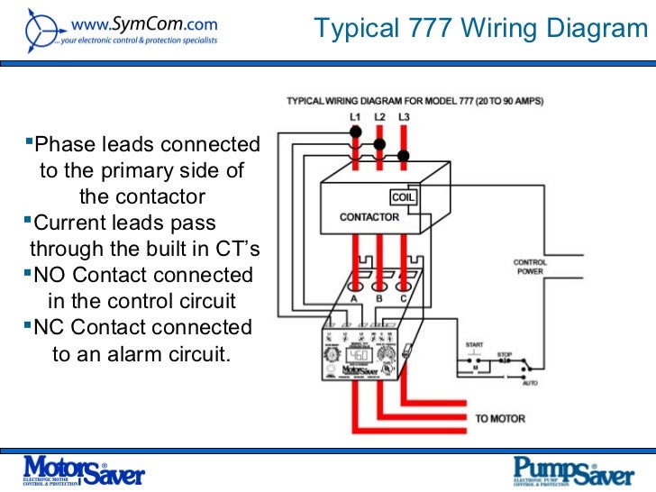
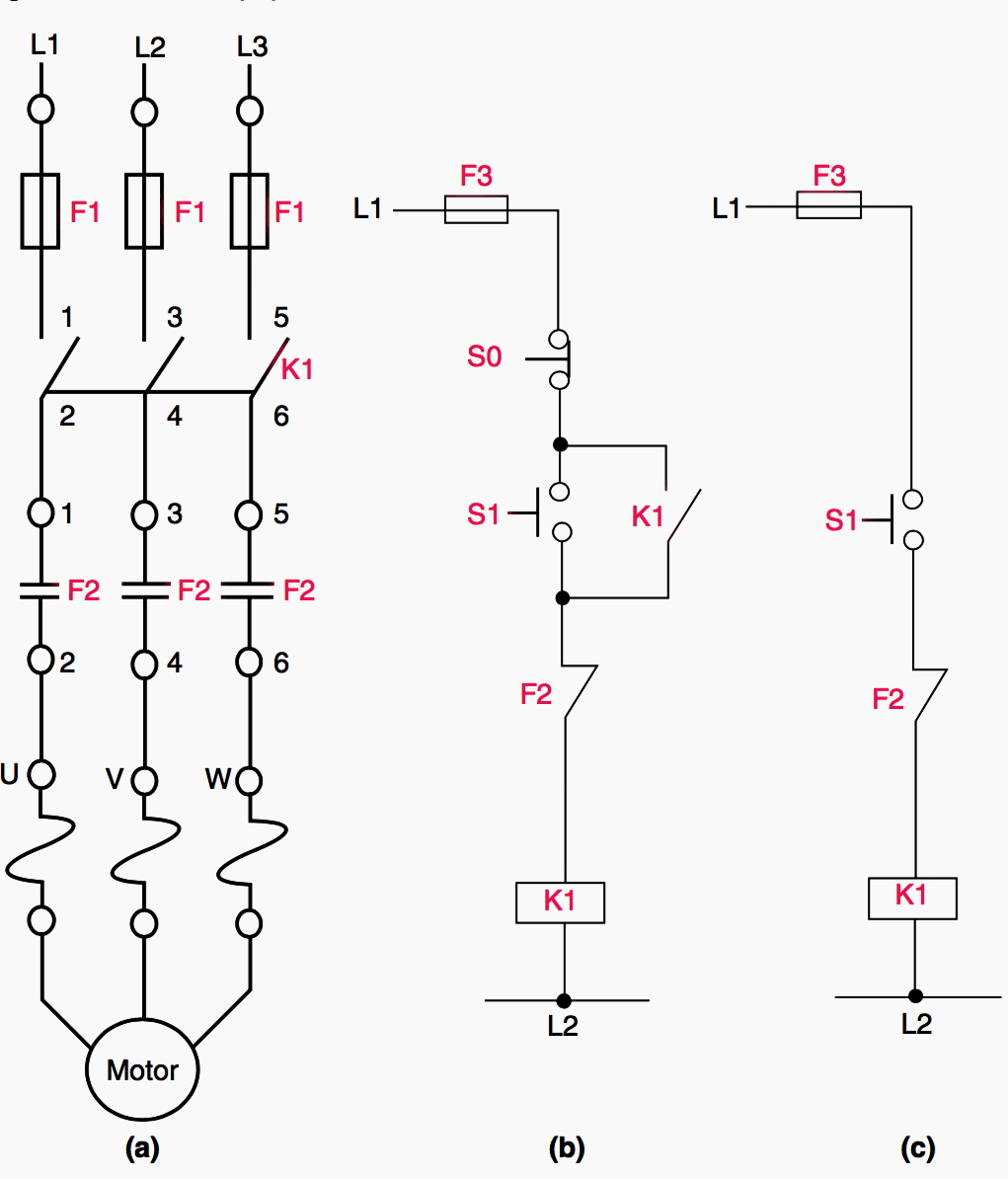
Collection of 3 phase electric motor starter wiring diagram. A wiring diagram is a streamlined conventional pictorial depiction of an electrical circuit.
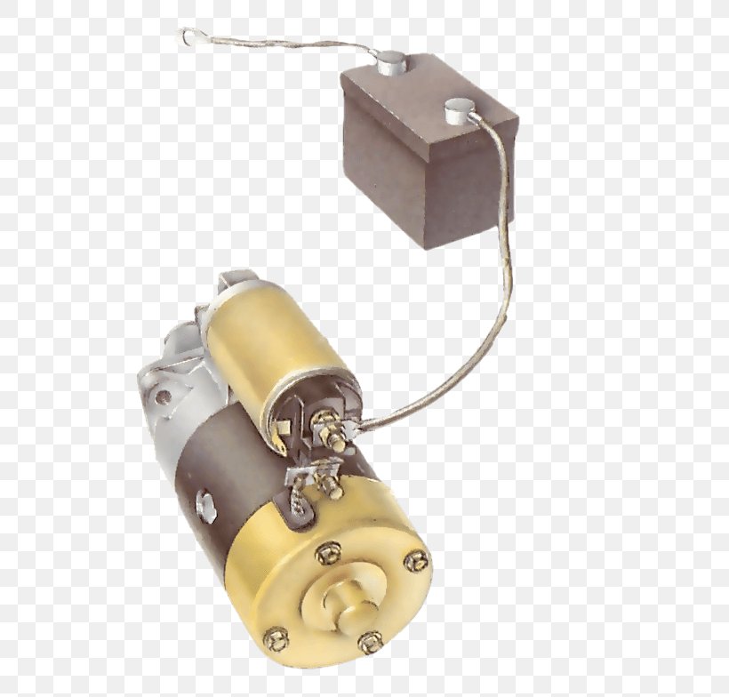
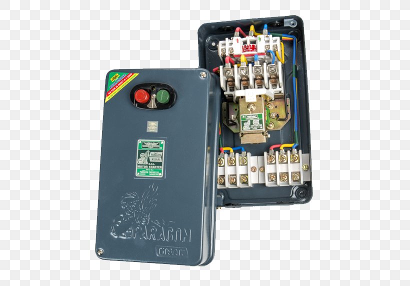
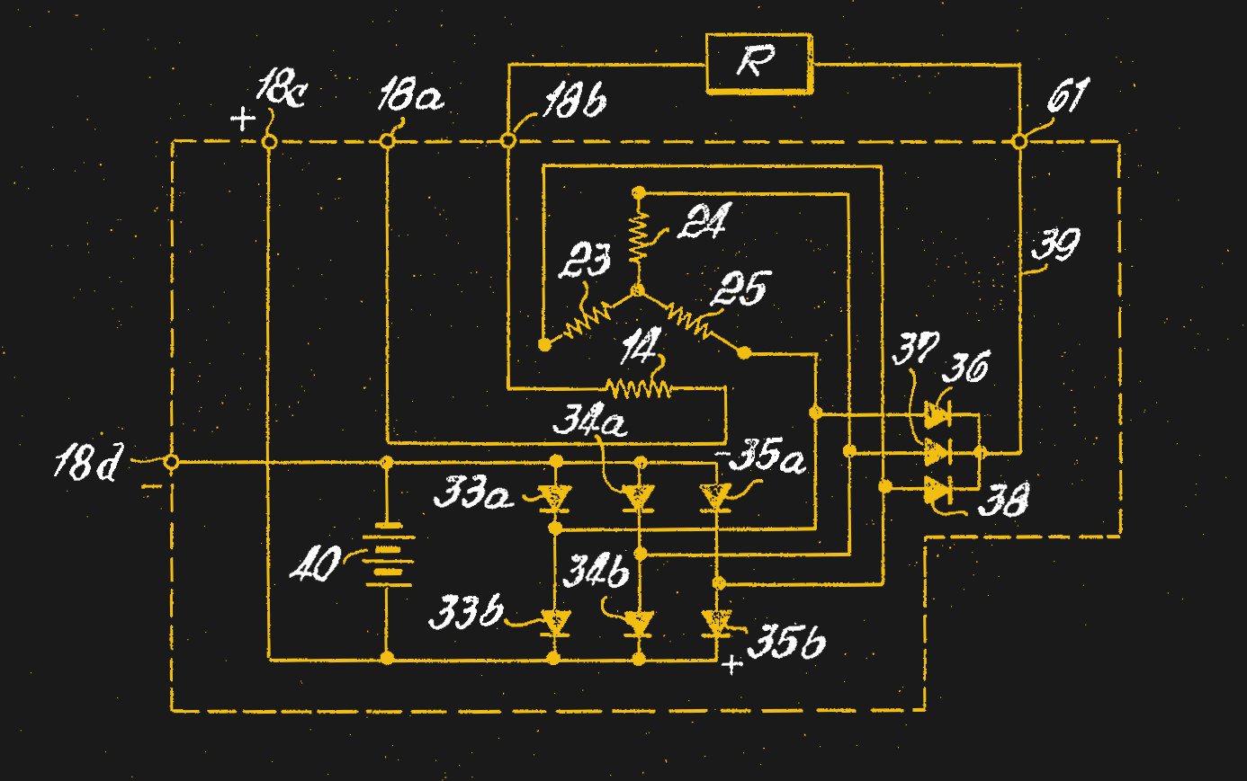
Car Starter Electronic Circuit Engine Wiring Diagram Png
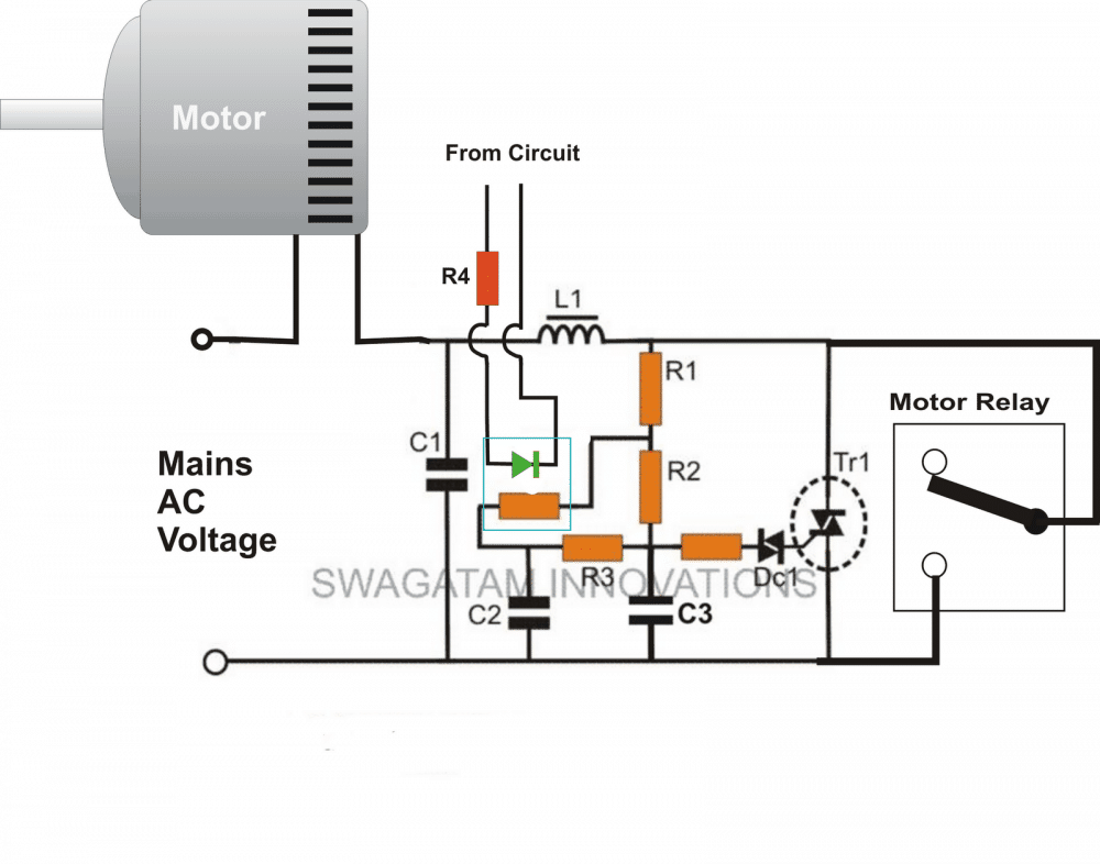
Electronic motor starter circuit diagram. This motor starter protects singlephase motors against voltage fluctuations and overloading. When the stator windings of an induction motor are connected directly to its 3 phase supply a very large current 5 7 times full load current flows initially. Its salient function is a soft onoff electronic switch for simple operation. Three phase motor connection stardelta without timer power control diagrams. If you are not sure of how to make the connections on your equipment hire an electrician. The transformer steps down the ac voltage from 230v to 15v.
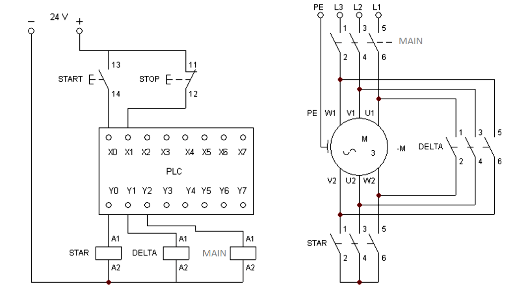
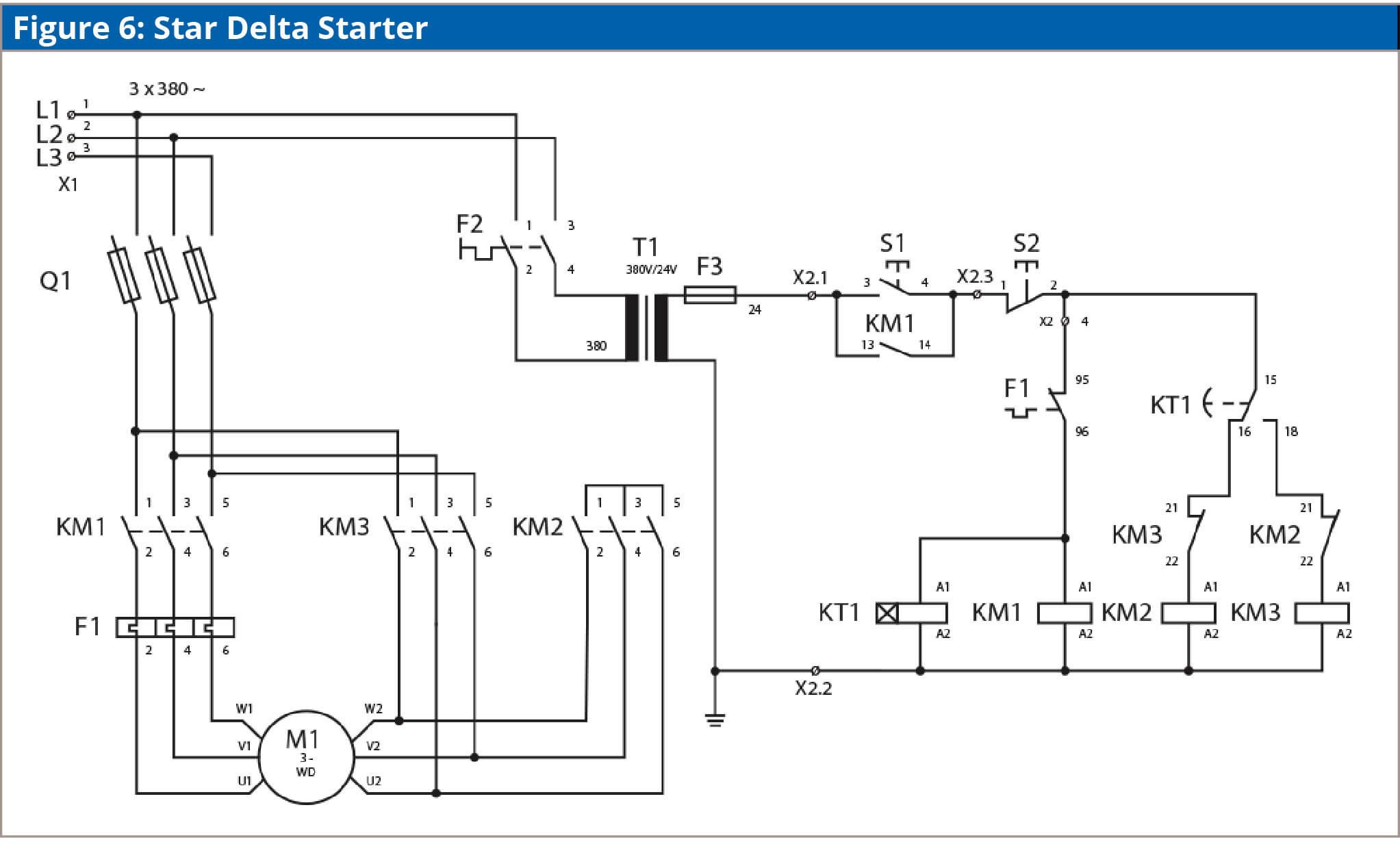
Star delta y δ 3 phase motor starting method by automatic star delta starter with timer. Three phase motor connection schematic power and control wiring installation diagrams. Induction motors started with direct on line dol starter. Four point manual dc motor starter circuit diagram. Ask your students to identify any motor control circuit diagrams theyve already seen as being across the line if there are no convenient motor control circuit diagrams available for illustration you may want to ask a student to draw an across the line starter circuit on the whiteboard for everyone to see. This surge current reduces as the motor accelerates up to its running speed.
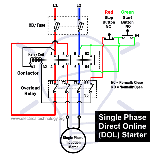
The above diagram is the schematic diagram of an electronic motor starter circuit. Please refer to the manufacturers literature if in doubt. In the above one phase motor wiring i first connect a 2 pole circuit breaker and after that i connect the supply to motor starter and then i do cont actor coil wiring with normally close push button switch and normally open push button switch and in last i do connection between capacitor. Feb 5 2020 explore elects agass board electrical diagram on pinterest. It reveals the parts of the circuit as simplified shapes and the power as well as signal links between the gadgets. Your motor starter may use wiring which is internal to the starter wiring which is different than the diagrams etc.
Figure 4 shows the automatic dc starter circuit diagram. Ac manual starters and manual motor starting switches 12 class 2510 12 class 2511 and 2512 13 2 speed ac manual starters and. An automatic starter operates in a similar fashion except that automatic relays short out sections of the starter resistance either by a time sequence or when the armature current drops to a selected value. All diagrams are intended to illustrate the logic of a latching contol circuit. See more ideas about electrical diagram electrical circuit diagram electrical engineering. Wiring diagram book a1 15 b1 b2 16 18 b3 a2 b1 b3 15 supply voltage 16 18 l m h 2 levels b2 l1 f u 1 460 v f u 2.
The above diagram is a complete method of single phase motor wiring with circuit breaker and contactor.
