This circuit has many applications on places where it is necessary to activate and deactivate connect and disconnect an electrical or electronic device. See more ideas about electrical diagram electrical circuit diagram electrical engineering.
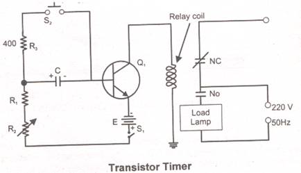
Transistor Timer
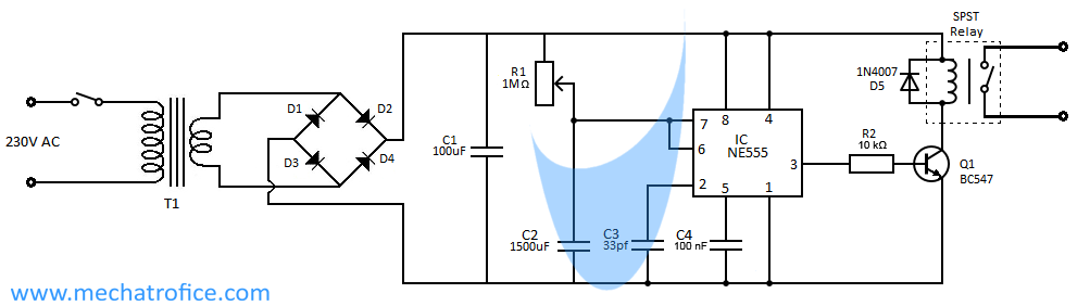
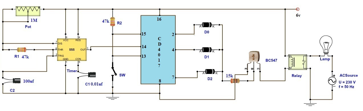
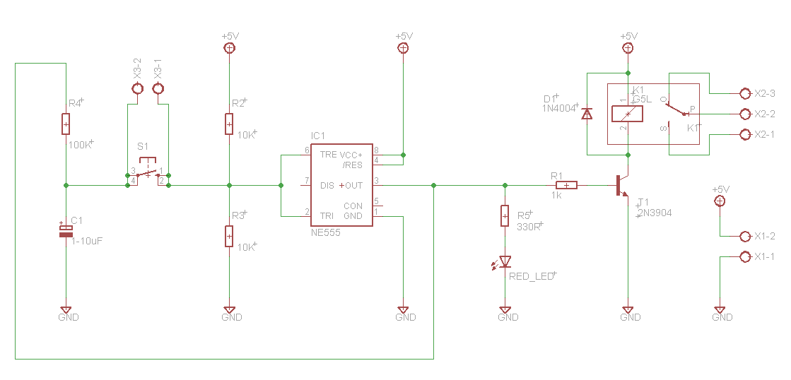
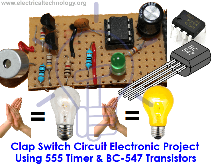
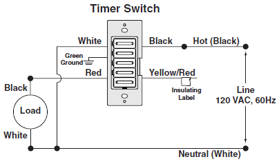
Electronic timer switch circuit diagram. This on off switch circuit using a 555 timer is simple useful and easy to implement. The 555 timer is used in mono stable mode and these pulses are applied to ic cd 7490 decade counter. Hello guysin this video i will show you how you can make a simple 220v ac timer switch at home without using any ic. By using timer switch you can easily control your appliances. Let us discuss in detail about this circuit. Clap switch is an interesting hobby circuit which turns on the lights with a clap sound.
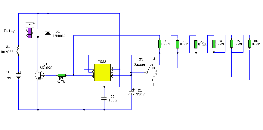
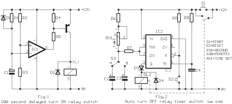
This circuit uses very basic components like 555 timer and 4017 counter. This timer circuit is designed to switch on a 12 v load in a solar powered installation for a preset period at the press of a button. These circuits can be used for variety of timing purposes in electronic projects like time delay relay etc. Using versatile ic 4060. When the period has expired a latching relay disconnects both the load and the controller circuit from the 12 v supply. Adjustable on off timerusing 555 astable mode in this circuit a timer with cyclic on off operations is designed.
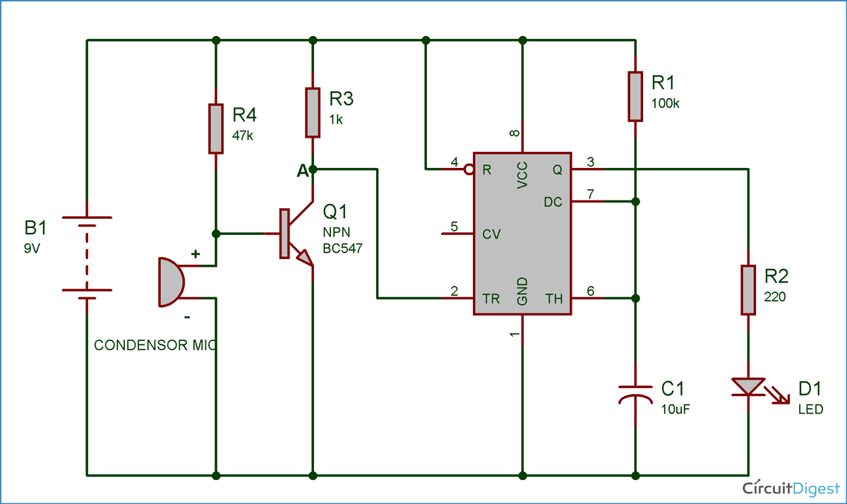
Feb 5 2020 explore elects agass board electrical diagram on pinterest. Hence the name 9 way clap switch. These lights can be used to place in front of the car. On off switch circuit using a 555 timer. Although its name is clap switch but it can be turned on by any sound of approximately same pitch of clap soundthe main component of this clap switch circuit is the electric condenser mic which has been used as a sound sensorcondenser mic basically converts sound energy into electrical energy. Led running lights circuit can also be called as knight rider circuit.
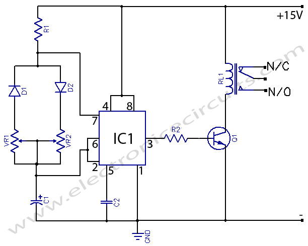
This circuit uses 555 timer and cd4017 counter. The on time delay and the off time delay are independently settable and this facility becomes the most important feature of a programmable timer circuit. Led running lights circuit. In other words if you are looking for an automated device to work for a certain time period and switch off after the desired time then this timer circuit is the best choice to opt. These on off intervals can be adjusted by varying the 555 timer output and number of counter outputs. In this page we will discuss a very simple yet reasonably useful timer circuit diagram whose on time and off time settings are independently adjustable through.
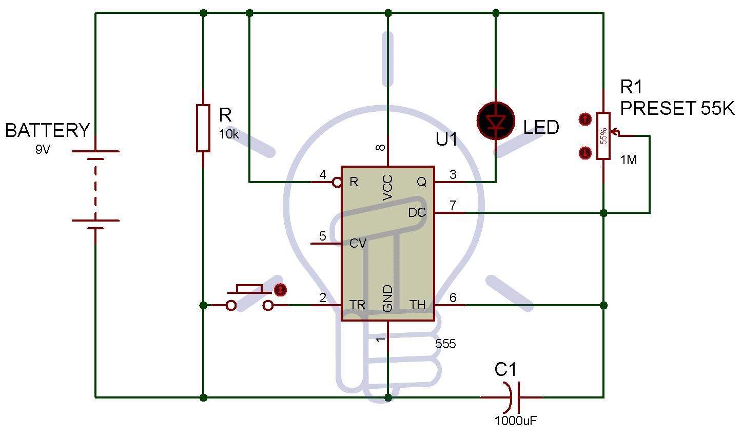
The figures below show different schematics of simple timer circuits which can be built very easily with few general components. A simple timer circuit can be built by using only a single or two transistors. In this project we are using 555 timer ic to create various timer circuit like 1 min timer circuit 5 min timer circuit 10 min timer circuit and 15 min timer.
Gallery of Electronic Timer Switch Circuit Diagram