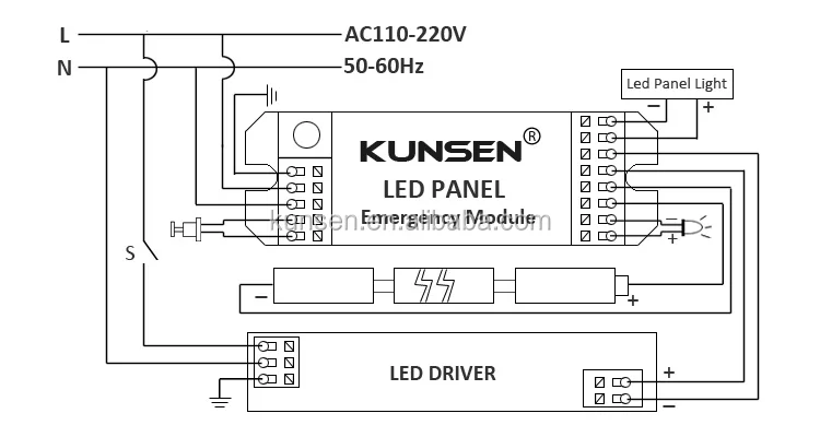
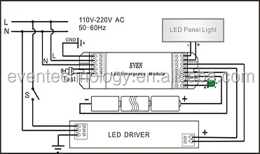
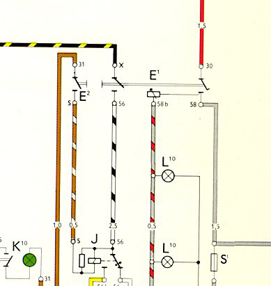
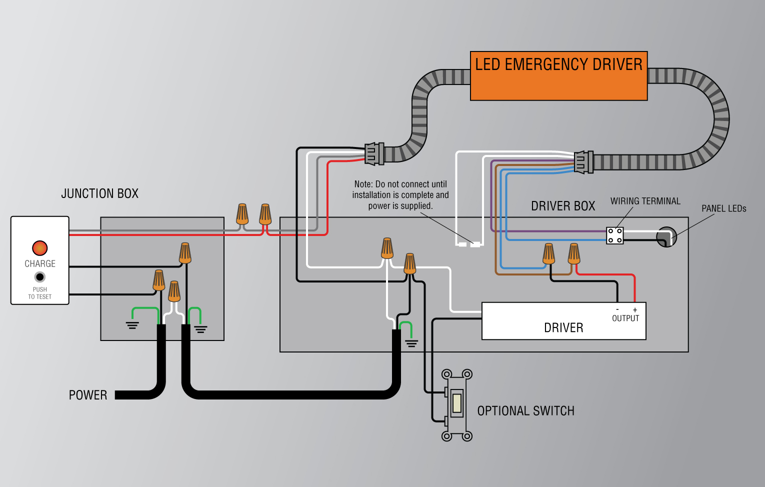
Emergency key switch wiring diagram wiring diagram is a simplified agreeable pictorial representation of an electrical circuit. This diagram illustrates wiring for one switch to control 2 or more lights.

Nema 7 9 Class 1 Division 1 Emergency Light
Emergency light switch diagram. Use the navigation window and select the emergency ballast for which the diagram is needed then scroll through the list of applications to find the. It shows the components of the circuit as simplified shapes and the capacity and signal links together with the devices. Also read the related post. The second circuit is the emergency lights circuit using leds. I have divided the circuit into two parts. Switch box test switch charge light black yellow yellow white unswitched switched or unswitched line common blk 120v white lamp ac emergency black white blue red blue bluewht.
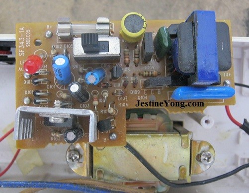
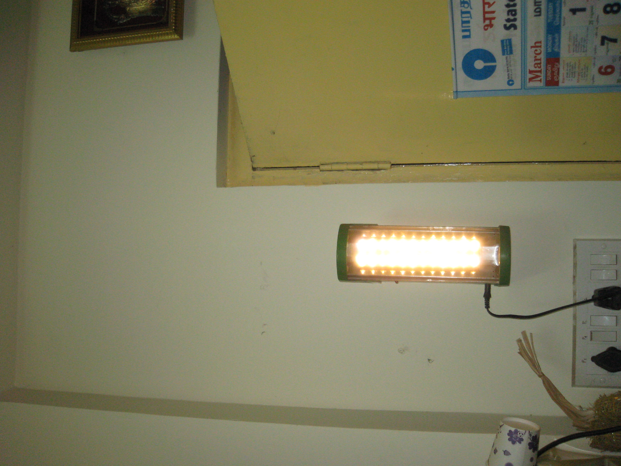
Automatic washroom light switch circuit. The first one is the battery charging circuit which also acts as an indicator circuit if the mains supply is shut down. The hot and neutral terminals on each fixture are spliced with a pigtail to the circuit wires which then continue on to the next light. Automatic emergency light circuit diagram. The source is at sw1 and 2 wire cable runs from there to the fixtures. The purpose of emergency lighting is to ensure the lighting is provided promptly automatically and for a suitable time when the normal power supply to the lighting fails to ensure that people.
Multiple light wiring diagram.
