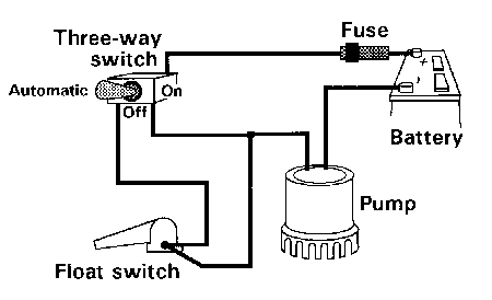
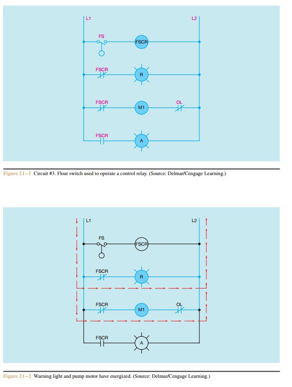
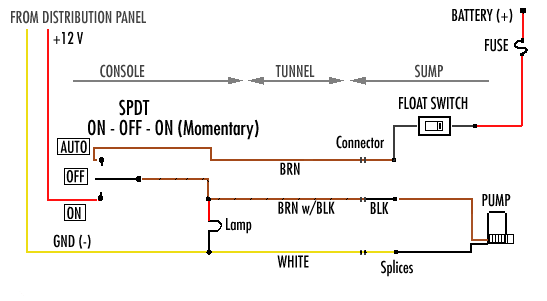
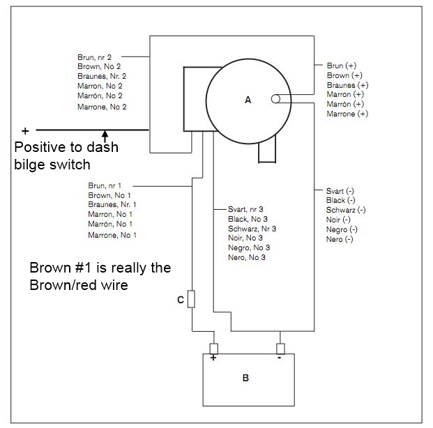
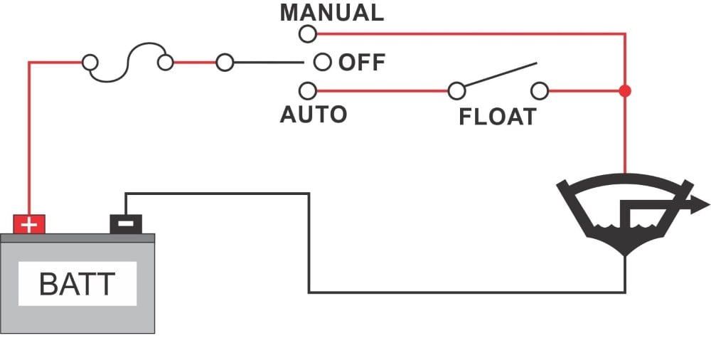
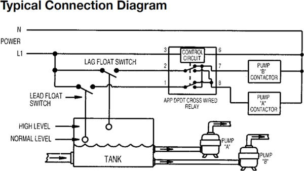
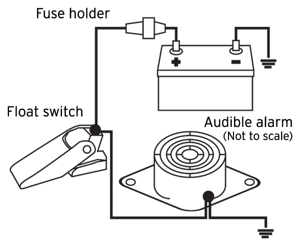
Hello friends in this video i will tell you how to make the. Collection of float level switch wiring diagram.

Kn 1378 Float Switch Wiring Diagram Free Diagram
Float switch connection diagram. For example water level controls is a float switch manufacturer that is revolutionizing the way float switches are used for water level sensing. Float switches of the 21st century have come much further in the amount of operations your float switch can perform. In this video how to use float switch wiring single phase on off motor using float switch diagram installation for water tank. How new float switches work. It reveals the parts of the circuit as simplified forms as well as the power and signal links in between the tools. Septic tank float switch wiring diagram septic tank 3 float switch wiring diagram septic tank float switch wiring diagram every electrical arrangement is made up of various diverse components.
Water level controls new float switches work by using probes instead of floats to detect or sense. Lets start with the most basic float switch. A wiring diagram is a simplified standard photographic representation of an electric circuit. If not the arrangement will not work as it ought to be. A two wire single pole single throw float switchthe rising action of the float can either close ie turn on a normally open circuit or it can open turn off a normally closed circuitinstallation scenarios might include a normally open float switch turning on a pump to empty a tank control schematic 2 or a normally closed. Each part ought to be set and connected with different parts in particular manner.

