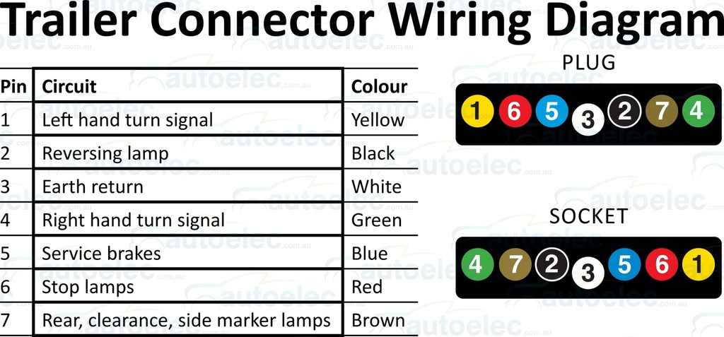
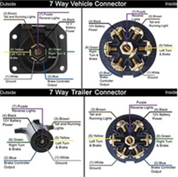
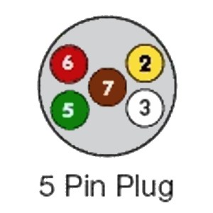
When we refer to the socket we are talking about the side of the vehicle where we make the connection while the plug is the trailer side. If your truck has a built in 7 pin socket but you only need 5 of the pins.
Trailer Wiring Diagrams Exploroz Articles
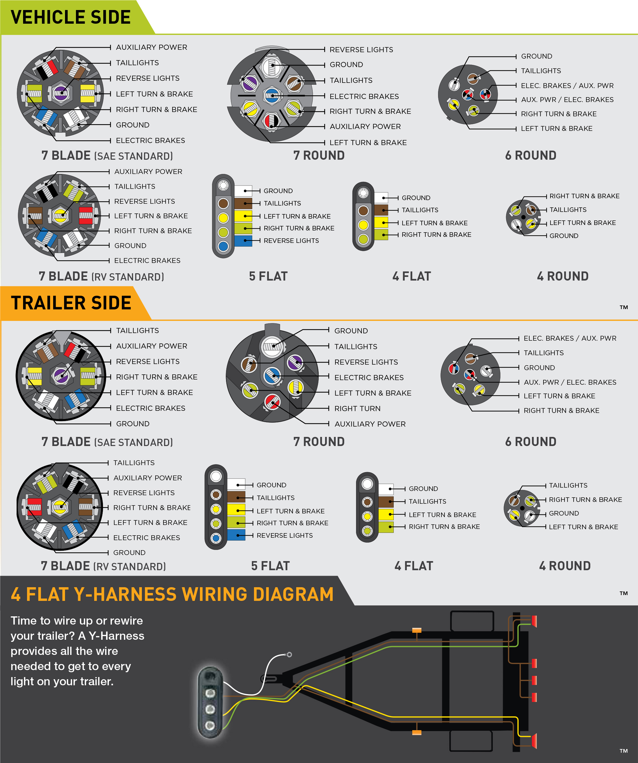
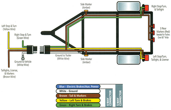
Trailer socket diagram. For a utility trailer we use a four way system. You will need twin electrics if you require more power than what a single 7 pin socket can provide on a pre 2008 manufactured uk caravan post 2008 uk caravans are fitted with 13 pin connectors. For a boat we use a five way system. They often use bonded wires for a reliable connection and have rubber construction to protect against the elements. Use the 7 pin connector anyway see below and just leave out the last 2 wires. They can be purchased as a standalone plug for the truck or trailer or as a complete loop with both the plug and the socket included.
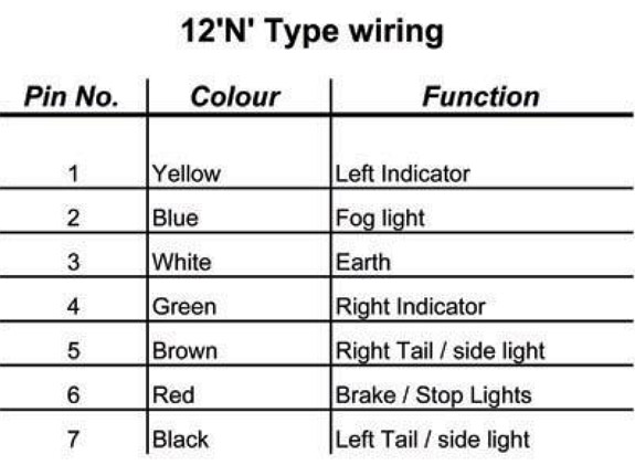
Trailer connectors between the trailer and passenger car light truck or heavy trucks with 12v systems in europe both 7 pin iso 1724 and 13 pin iso 11446 are common. For a boat trailer we use a four way cable system. This is the standard uk wiring of a the normal socket and plug otherwise known as 12n. And for a trailer. To connect the electric system of your trailer to the vehicle you will be using special connector. This supplies power to the road lighting of your trailer or caravan.
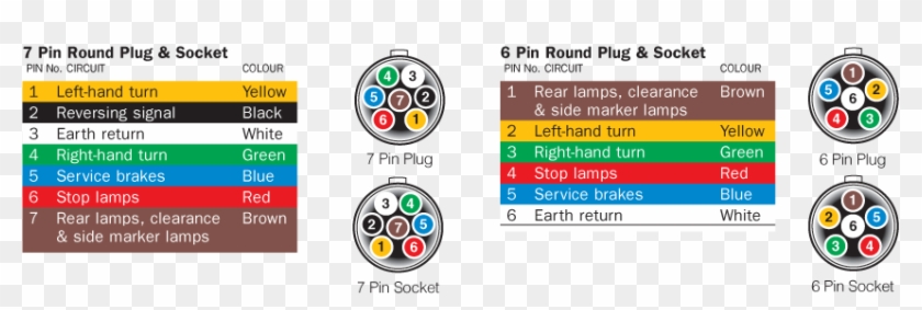
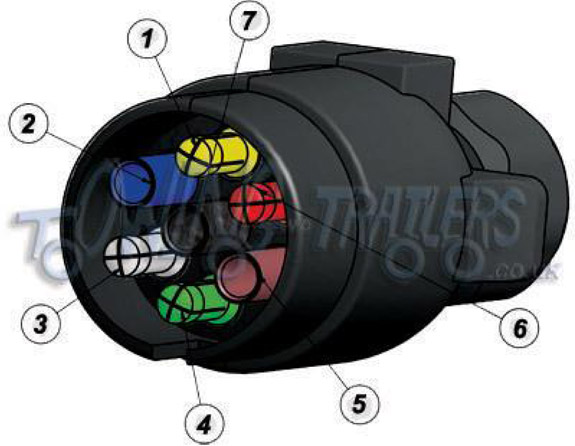
Below is a diagram for the original plug and socket showing the functions of each pin. Twin electrics is a 2 plug system which combines the single 7 pin 12n electrics socket with a 12s electrics socket. And we offer so much more than that. Above we have describes the main types of trailer wiring diagrams. The wiring is very similar the only difference is the 5 way will. This has now been replaced by 13 pin euro plugs on all new caravans.
For a caravan trailer we use a seven way system. The 7 pin n type plug and socket is still the most common connector for towing. The 13 pin version being phased in is newer provides more services than the 7 pin a more positive locking and also better protection against moisture and contamination. Complete with a color coded trailer wiring diagram for each plug type this guide walks through various trailer wiring installation solution including custom wiring splice in wiring and replacement wiring. Stop into our harrisburg pa dealership today or call to learn more. Below is the generic schematic of how the wiring goes.
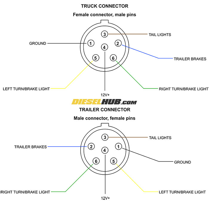
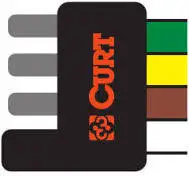
Were happy to help guide our customers to the right trailer or snow plow for them. If your vehicle is not equipped with a working trailer wiring harness there are a number of different solutions to provide the perfect fit for your specific vehicle. In the trailer wiring diagram and connector application chart below use the first 5 pins and ignore the rest. The diagram below shows the view from outside the vehicle socket under the flap and from inside the trailer or caravan plug. 4 pin trailer wiring diagram.


