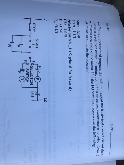
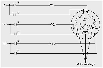
Make the example ladder logic to control the motor in forward and reverse direction using plc programming with limit switches as sensors. Plc example for motor.
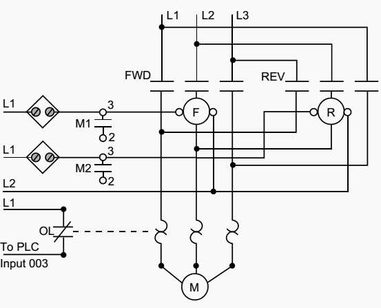
Plc Implementation Of Forward Reverse Motor Circuit With
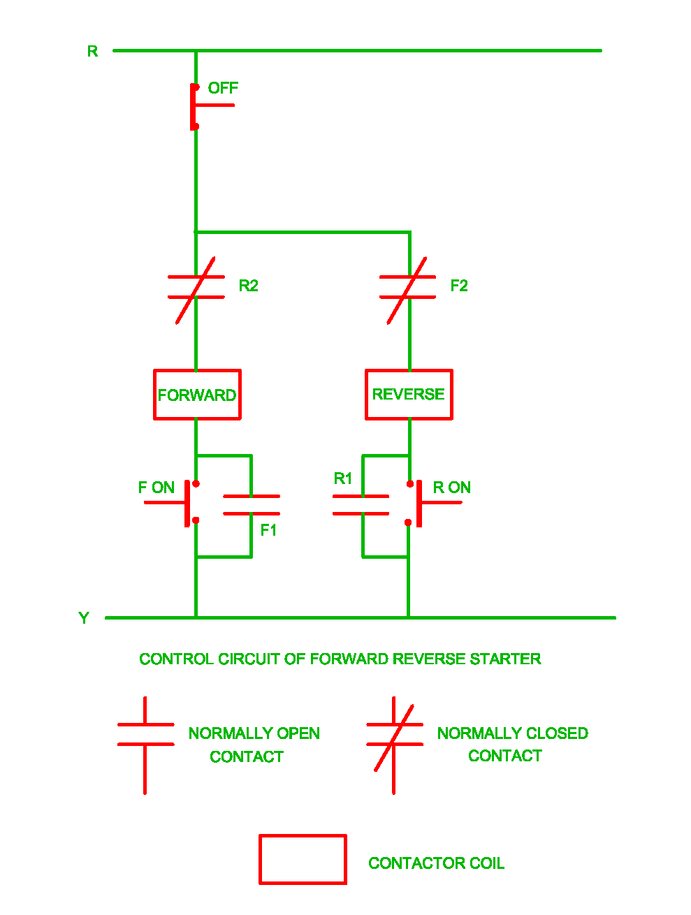
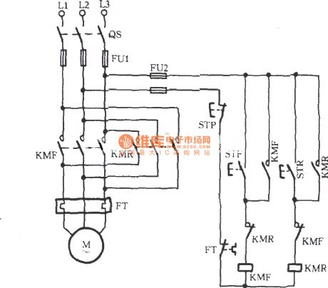
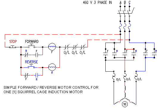
Forward reverse motor starter. In this article we are going to learn about the forward reverse starter. Forward reverse starter diagram. These two normally open push button switch shown with green color. Working of forward reverse starter control circuit forward direction. Press on push button f on the forward contactor coil gets supply through phase r off push button r2 forward contactor coil on push button f phase y. Single phase forward reverse motor wiring diagram concerbiz size.
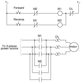
Your question is about the control circuit which is the wiring to the push buttons andor switches and other devices that turn on a motor and choose which direction it will run. The reverse contactor coil energized and three phase induction motor runs in the reverse. Here are a few of the leading drawings we obtain from various sources we wish these pictures will serve to you and with any luck very appropriate to just what you want about the reversing motor starter wiring diagram is. The workpiece starts moving on the left side and moves to the right when the start button is pressed. Note that the motor circuit also uses the overload input which will shut down the motorthe normally closed overload contacts are programmed as normally open in the logic driving the motor starter outputsthe forward and reverse motor commands will operate normally if no overload condition exists because the overload contacts will provide continuity. I shown the 3 pole mccb circuit breaker 2 magnetic contactor normally open normally close push button switch thermal overload relay 3 phase 4 wire system supply 3 phase motor with connection trip indicator light etc.
In the 3 phase motor forward reverse starter wiring diagram. 800 x 600 px source. Wired through your emergency stops then manual stop then start with a. As the name defines forward reverse starter is used to run the motor in both sides forward and reverse. In the diagram i shown also a light indicator which will be one when the motor thermal overload relay trip due to motor getting over current. In short this the complete guide of forward reverse starter.
Control circuit for forward and reverse motor checkout video on 4 way switch wiring. Forward green switch is use for to run motor forward and reverse switch is used for run motor on reverse mode. The figure given below shows the control and power diagram of forward and reverse starter diagram.


