Gfci Line Load Diagram

It is important to know which is which before beginning. Gfci load wiring diagram.

Gfci Load Wiring Electrical 101

Gfci Load Wiring Electrical 101

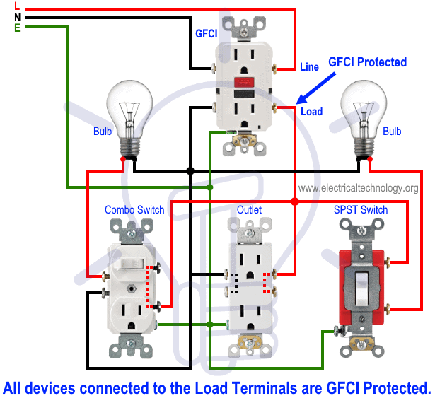
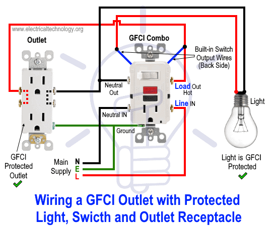
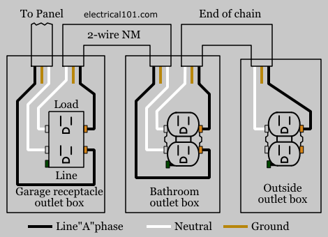
Gfci line load diagram. Select either image to enlarge. The gfci receptacle will have line and load areas to attach your wires to. Ground fault circuit. In the following diagram the above load mentioned before ie. Protected receptacles will be connected to the gfci load side as shown below. Connecting to the line terminals only results in the outlet providing gfci protection only for that outlet.

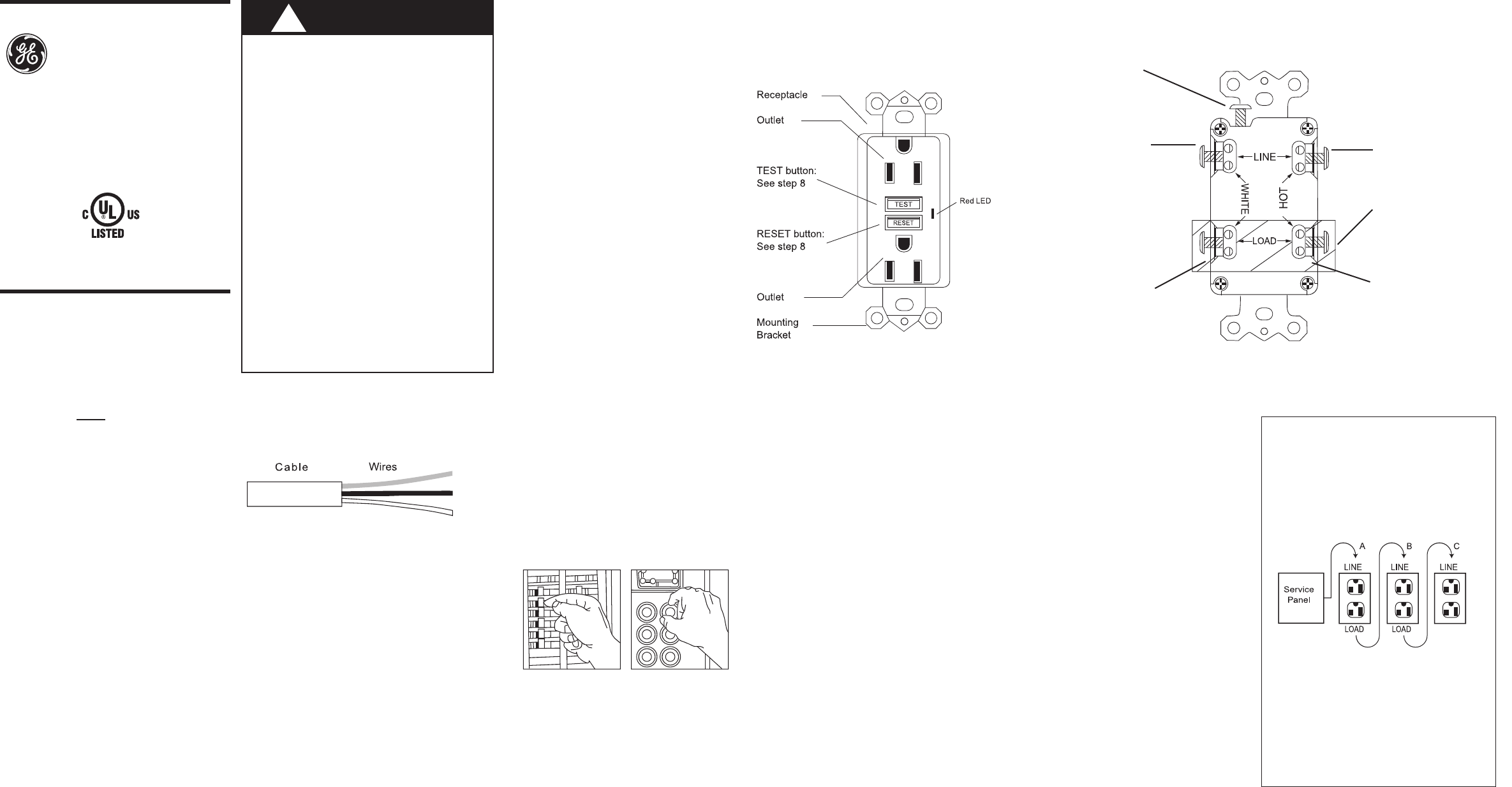
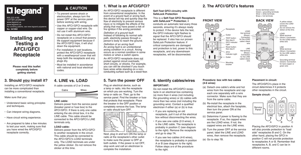
Also inspect the load side black and white conductors for damage and make sure the ground conductor is not coming into contact with any other screws on the receptacle. About wiring to line and load on the receptacle diagram. The line terminals and the load terminals. Gfcis have two pairs of screw terminals for connecting wires. When it comes to ground fault circuit interrupter or gfci outlets there is always a question as to how to connect the wiresthis is because gfcis have two different sets of terminals. Components and devices are connected to the line terminals of gfci ie.

One pair is marked line and one is marked load. Line and load have special meaning when wiring ground fault circuit interrupter gfci outlets. This way the combo switch outlet light switch and ordinary outlet are not gfci protected. The back of these outlets are clearly marked line and load. Power is connected to the gfci line side. When you connect only to the line terminals the outlet provides gfci protection only for itself.

The line is the set of wires coming from the panel or power source the load is the wire set leaving the receptacle box to the other downstream receptacles to be controlled by the gfci. They are connected to the direct main supply.

Gallery of Gfci Line Load Diagram

How To Wire A Gfci Outlet Gfci Wiring Circuit Diagrams
Download Now
How To Wire A Gfci Outlet Gfci Wiring Circuit Diagrams
Receptacle Gfci Wiring Diagram Wiring Diagram
Download Now
Receptacle Gfci Wiring Diagram Wiring Diagram
Cl 4254 Gfci Wiring Diagram Series Wiring Diagram
Download Now
Cl 4254 Gfci Wiring Diagram Series Wiring Diagram
Why Do Gfci Outlets Have 4 Lead And 4 Load Holes
Download Now
Why Do Gfci Outlets Have 4 Lead And 4 Load Holes
Diagram Wiring Multiple Gfci Schematics C3 Wiring Diagram
Download Now
Diagram Wiring Multiple Gfci Schematics C3 Wiring Diagram
F7f3 Wiring Diagram For Gfci Circuit Wiring Library
Download Now
F7f3 Wiring Diagram For Gfci Circuit Wiring Library
Wiring Multiple Gfci Outlets
Download Now
Wiring Multiple Gfci Outlets
Ge Appliances 51960 Ground Fault Circuit Interrupter Quick
Download Now
Ge Appliances 51960 Ground Fault Circuit Interrupter Quick
Cooper Gfci Schematic Wiring Diagram H1 Wiring Diagram
Download Now
Cooper Gfci Schematic Wiring Diagram H1 Wiring Diagram
Mw 240v Spa Gfci Box Disconnect Up To 50a Load
Download Now
Mw 240v Spa Gfci Box Disconnect Up To 50a Load
Radiant Afci Gfci English
Download Now
Radiant Afci Gfci English
Need Help With Gfci Switch Combo Only Two Wir Leviton
Download Now
Need Help With Gfci Switch Combo Only Two Wir Leviton
Gfci Trips Immediately
Download Now
Gfci Trips Immediately
Wire Diagram For Gfci Wiring Diagram
Download Now
Wire Diagram For Gfci Wiring Diagram
Light Switch Wiring Load Simple Gfci Outlet With Switch
Download Now
Light Switch Wiring Load Simple Gfci Outlet With Switch
Wire Diagram For Gfci Diagram Base Website For Gfci
Download Now
Wire Diagram For Gfci Diagram Base Website For Gfci
3 Phase Gfci Wiring Diagram H1 Wiring Diagram
Download Now
3 Phase Gfci Wiring Diagram H1 Wiring Diagram
How To Wire Gfci Combo Switch Amp Outlet Gfci Switch Outlet Wiring
Download Now
How To Wire Gfci Combo Switch Amp Outlet Gfci Switch Outlet Wiring
Gfci Load Wiring Electrical 101
Download Now
Gfci Load Wiring Electrical 101